Warbirds in my Workshop

David Glen BSc (Hons) MSc, Model Maker, Journalist and Author

Formerly Spitfire in my Workshop

Machining the main landing wheels


Wednesday, 29th August, 2018

Forgive me if my diary keeping has become erratic in its chronology: In my most recent posts I’ve been describing work in July and August, while for this latest episode I revert back to May!  No matter. Better late than never.  

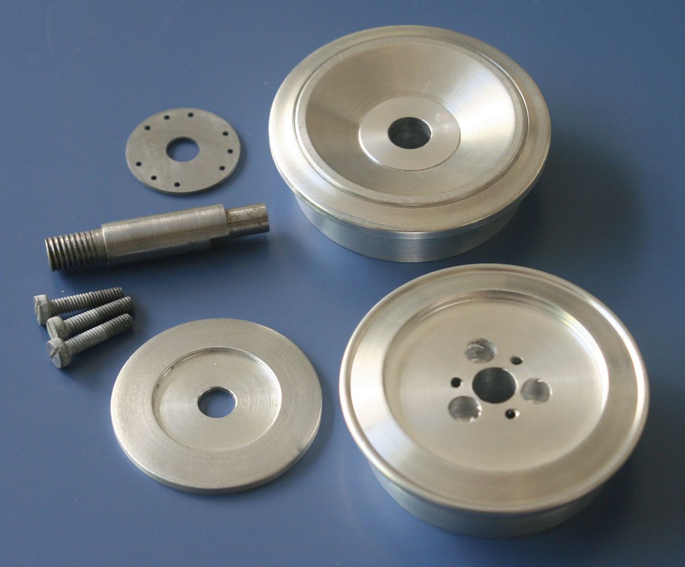
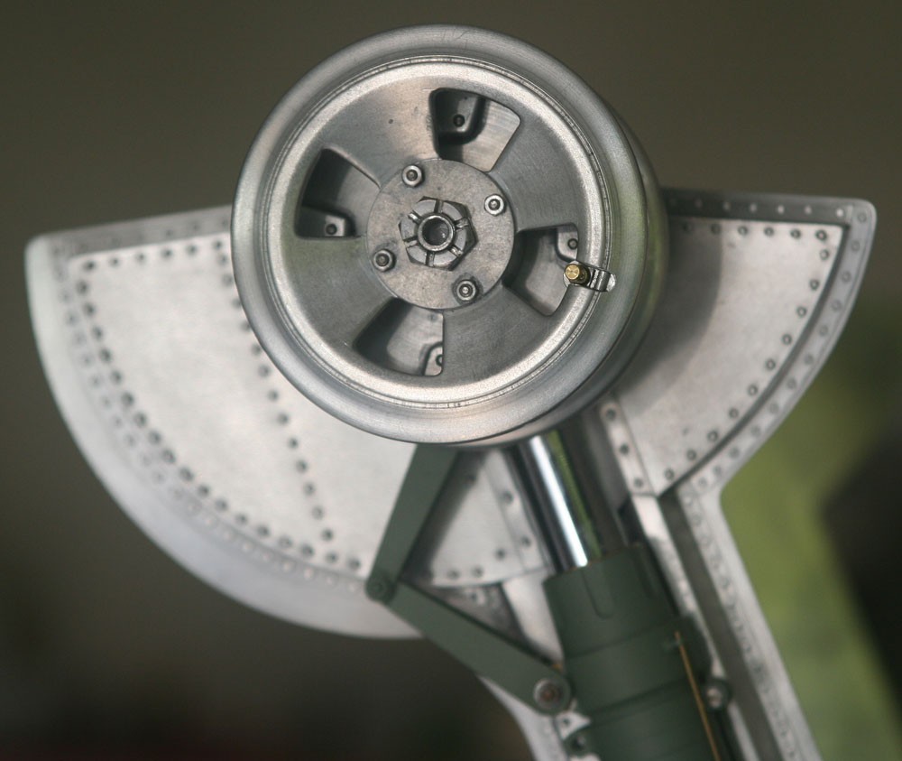
Machining the main landing wheels of a 1:5 scale Spitfire model out of solid 2.5-in diameter machine-grade aluminium bar is not a job to be approached lightly, and not least because significant planning is involved, principally in how to simplify the internal structure such that a home machinist operation becomes practicable, while at the same time preserving a semblance of realism for those determined to peer in between the spokes.

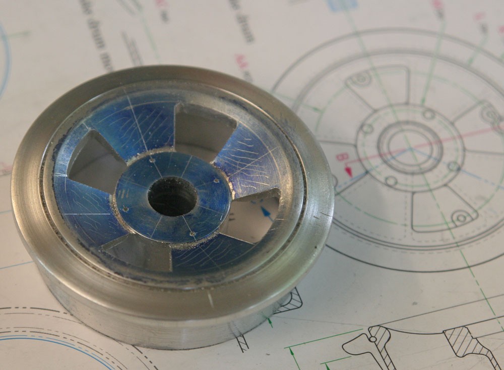
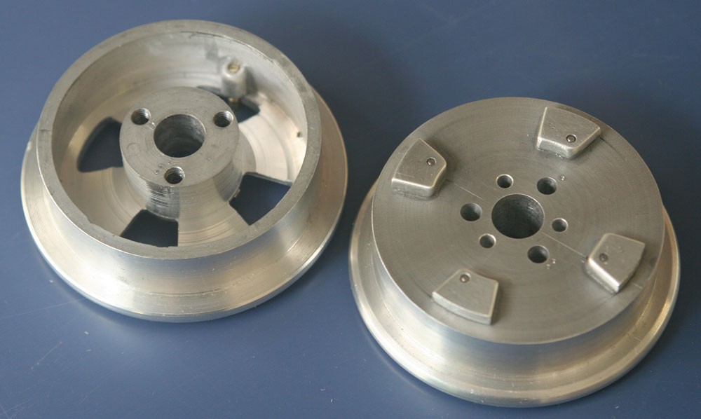
Paul Montforton’s drawing include excellent renderings of the three-, four- and five-spoke wheels, and I chose the middle option for my Mk IX.  The overriding starting criteria were that each wheel would have to be made in two halves and bolt together so as to enclose and ‘pinch’ the tyres and that the out-of-scale bolts would have to be hidden. The external surfaces, front and back, would be as true to the original as possible; internally, significant compromises would be made… and this is where the planning comes in.

In many respects what I describe here bears a close approximation to the comparable manufacture of the spoked wheels for my 1:5 scale P-51D Mustang, which I describe in my ‘P-51 Diary’  

http://www.spitfireinmyworkshop.net/story.php?id=18&title=machining-the-wheels

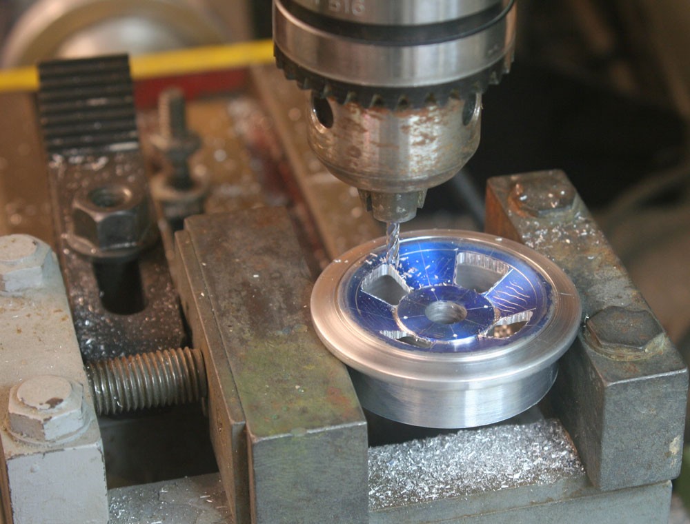
For that reason alone I’ll avoid going into great detail here, and let my pictures and captions do the talking…


Back to Spitfire Mk IX Diary

With the workpiece firmly clamped in my three-jaw chuck, the first operation is to drill the axle hole, following up with a reamer for a precision fit. I will be getting the front and rear halves of one wheel out of this section of 2.5-in. diameter bar. Yes, there's a lot of waste!
The front face of the wheel nears completion. Given my limited machinist's skills, parting off such a large diameter piece posed considerable problems, such that I was obliged to resort to a combination of machine parting followed by the crude application of a hacksaw!
Work at an advanced stage in turning the rear half of the same wheel. The outer facing side has been formed and the workpiece reversed in the chuck so that the mating face can be machined and much of the interior bored out. The conspicuous boss will be utiliesed for the three retaining bolts. This is a gross simplification of the architecture inside the full-sized version of the wheel!
Three holes have been drilled and tapped for the above-mentioned bolts. The additional three holes represent a failed first attempt!!
The principal components of one wheel. Note the inboard face has been recessed to accept the brake drum cover plate, which is represented by the tapered disc of aluminium adjacent to it. This provides a convenient means to hide the bolt heads, and it is itself recessed for the smaller steel plate (with its nine bolt holes) that is retained at the threaded end of the axle. Note that the opposite outer end of the axle has still to be machined to final length and threaded.
The milling machine comes in handy to rough out the spokes on the front face of the wheel, which are later refined by hand using a selection of files.
The workpiece checked against Paul Montforton's splendid drawings.
The four dummy bolting lugs that feature in the real thing are my only concession to interior detail.
The completed wheel mounted on its axle. Detail includes the big castelated wheel retaining nut and the air valve housing and valve cap. Any slight play in the wheel was taken out by shim washers.
Mustang in my Workshop book cover

Mustang in my Workshop

A book to inspire, encourage and empower the enthusiastic model maker to scratch build a masterpiece.