Installing the pilot's seat
Tuesday, 11th June, 2019
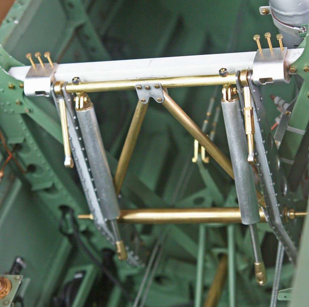
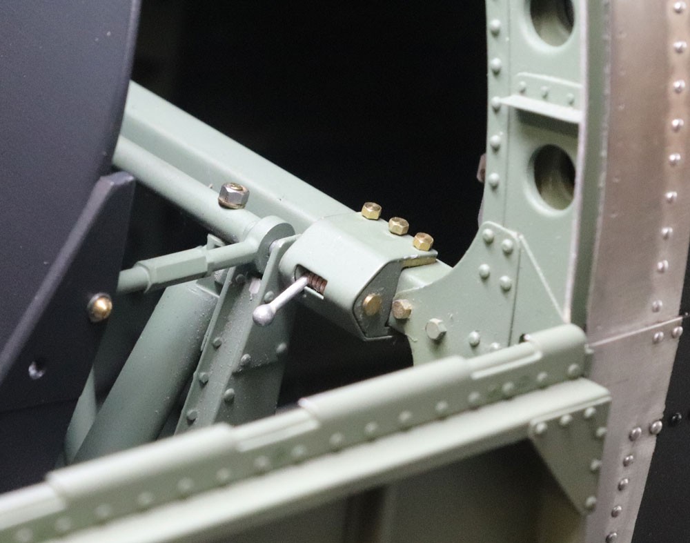
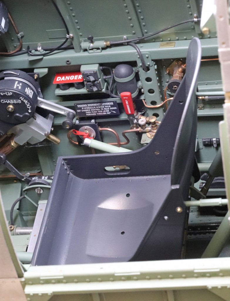
Broadly speaking, installation of the pilot seat of my model mimics full-size practise: The seat, pre-mounted on its sturdy support assembly, is lowered carefully into the cockpit until the brass pins projecting from the bottom of the vertical support beams engage into holes in their respective base plates located lowdown on fuselage frame 11. The entire seat assembly is then pivoted backwards and tilted slightly until the starboard of two upper horizontally-orientated pins engages into a small streamlined fixed retainer located at waist height on frame 11. Once aligned, the entire seat installation is then locked in place by means of a second similar, but in this case removable, ‘retainer’ at the port side. As my photograph shows, this is secured in position by three removable 14BA brass bolts.
What I have called for simplicity my ‘retainers’ are – in the full-sized aircraft – a pair of neat tent-shaped fittings, each housing a spring-loaded, lever-operated plunger that enables ground crew to remove and replace the entire seat and seat support quickly and easily.
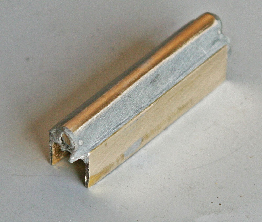
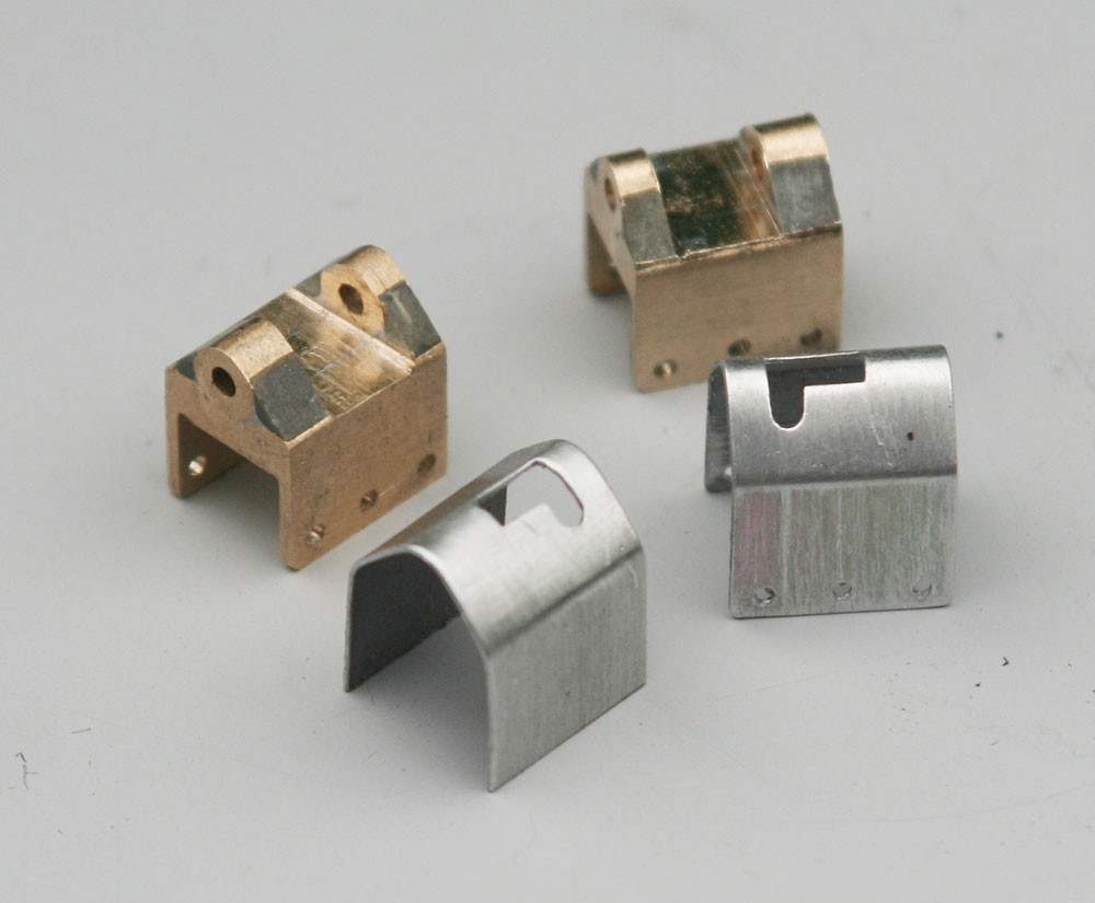
My versions feature the plungers, scale operating levers and even the visible portions of the internal springs. Yet even though they are not functional in the original sense, they nonetheless presented a challenge to make from scratch. However, with a little imagination and a small bench-top milling machine, I found that I was able to fabricate convincing replicas from relatively simple devolved parts – in this case some stock brass bar, brass tube, a little ‘plastic metal filler’ and a couple of scraps of printer’s plate. I trust my pictures are self-explanatory and that they help to drive home my oft-repeated mantra: With a little ingenuity, scratch building is not as difficult as it may seem.
