The sliding canopy frame
Monday, 20th April, 2020
The frame for my Spitfire’s sliding canopy is made of metal (litho-plate and 0.5 mm aluminium sheet) glued and screwed directly to the underlying clear plastic – a straightforward and basically simple process whereby the PETG and metal parts serve to stiffen and reinforce each other.
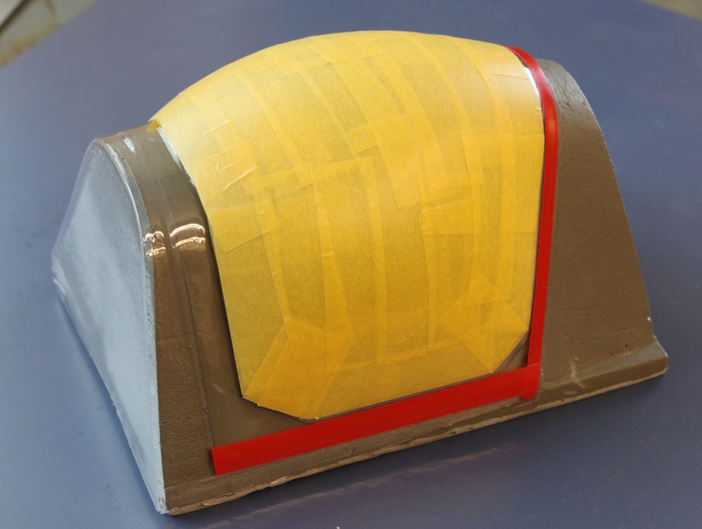
The only significant problem involved forming the canted channel-section frame at the front of the canopy: Here’s the technique that I used:
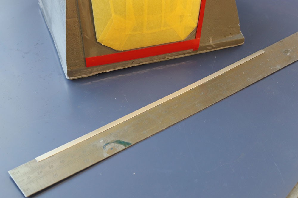
- Fold a length of unannealed litho-pate crisply around the edge of a 1mm thick steel rule.
- Mark and cut it to width (approximately 1/4-in.) with a sharp scalpel blade, first one side and then the other.
- Cautiously anneal the piece mid-way along its length, before inserting a strip of 1mm styrene into the open slot. This is to prevent distortion during the bending process.
- Form the arch shape, using the original resin tool as a pattern.
- Remove the styrene insert and measure and cut the ends of the formed workpiece to exact length.
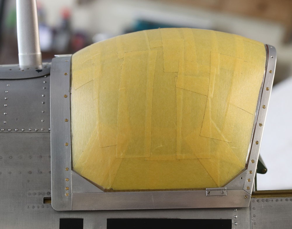
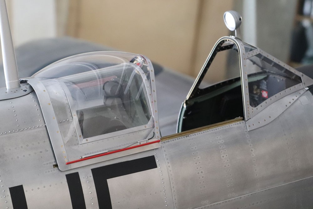
Once formed in this way, I fitted the delicate piece permanently by means of the numerous tiny 14BA x 3/32-in. retaining screws. These can be seen clearly in my photographs.
By comparison, the remainder of the frame, including the four triangular corner pieces, was very easy to make in the flat from 0.5mm alloy sheet. I used contact adhesive which is easy to apply precisely with a small disposable brush, and it does not cloud the crystal clear PETG.
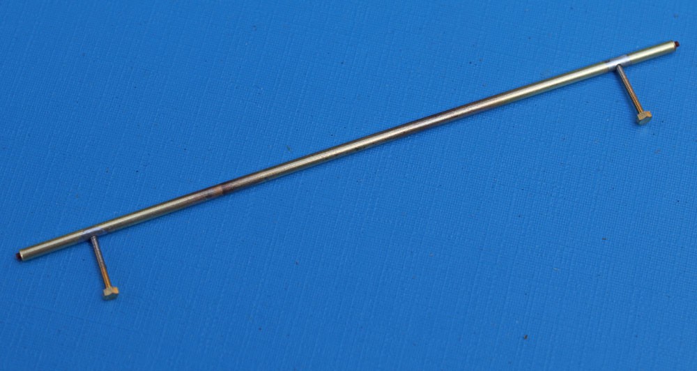
At this stage I took pains to check that the hood fitted correctly, and with particular attention to its alignment relative to the slotted rails embedded in the fuselage sides. I hit on a simple but effective surrogate for the ‘runners’, as can be seen in my photographs: two lengths of rectangular section styrene rod, one port and one starboard. As well as acting as spacers, these each carry two embedded countersunk steel screws. The screws, which protrude by about 1/8-in. at either end, fit perfectly in the slotted runners. This arrangement, aided by the innate springiness of the vac-formed canopy, retains the hood firmly in pace in the open position, while allowing it to be removed and replaced at will.
The detailed work began with the somewhat simplified emergency release arrangement along the bottom edges of the canopy. My pictures of this are largely self explanatory.
More challenging was the latch mechanism made almost entirely from tiny hand cut brass parts soft soldered with ‘solder paint’. Again I allowed myself the luxury of some simplification, but the end result looks credible enough, including the “pull to release” red ball, which is a spray painted bead plundered from my wife’s dress jewellery box.