The planning stage
Monday, 2nd September, 2013
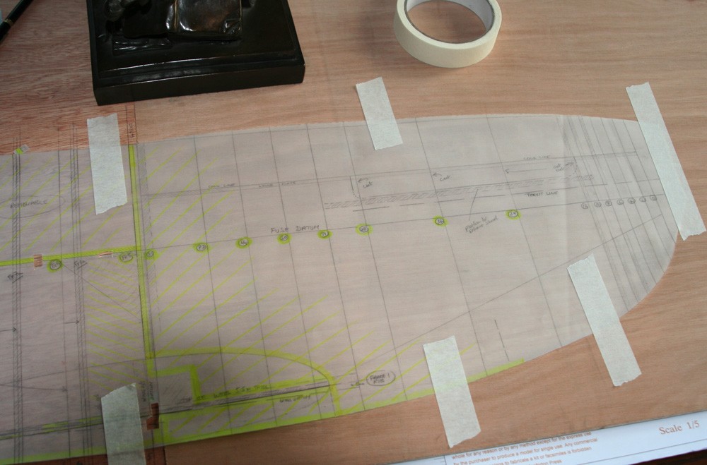
I bought the first sheets of plywood and began to trace the fuselage profile and cross sections in March of this year. Yet in terms of planning, the project started significantly earlier as I pondered on how I might ‘engineer’ a 1:5 scale model of a Spitfire Mk IX.
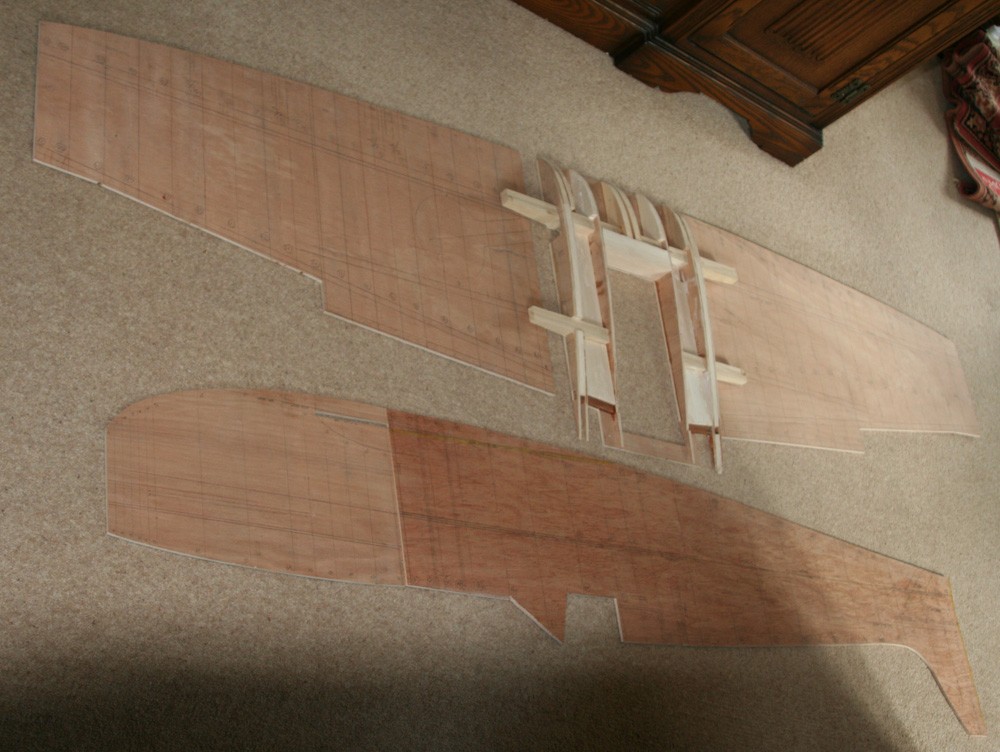
There had never been any doubt that I would approach the core of the model in much the same way as I tackled my Mustang, by creating the three-dimensional shape of fuselage and wings in plywood from the profiles and cross sections transferred from the drawing and filling the spaces between with balsa wood, thus creating a solid foundation onto which to form and bond the litho plate skin.
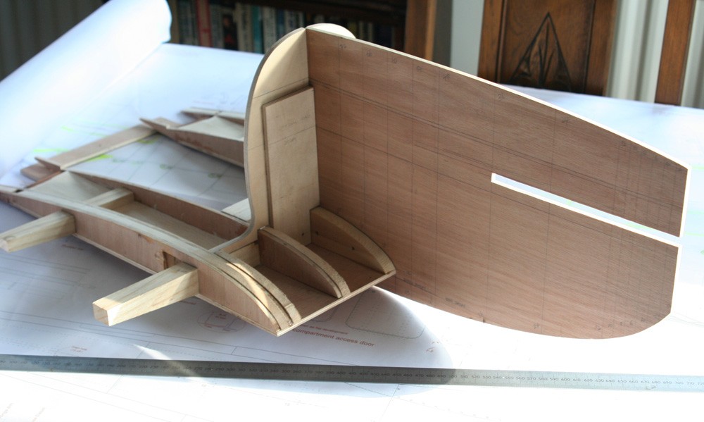
Chief among my concerns with the Spitfire, however, was to devise the means by which to support the wing. In the P-51D the fuselage more or less sits atop a one-piece wing, which simplifies things significantly. Not so with the Spitfire, where the port and starboard main planes are bolted either side of the fuselage, which essentially remains open all the way to the belly skin. Clearly, this was not practical in a model. In order to achieve structural strength I would need to devise a ‘false’ wing centre section, delineated by the dihedral break, and with at least one through-spar positioned so that it would not show.
But there were other fundamentals to consider: The significant upward bulge in the dorsal engine cowling, a characteristic of the Mk IX, meant that the entire nose section would have to be built separately from the main fuselage, and the pronounced lateral undercut above the exhaust stacks suggested that the top cowling itself be formed separately from the nose section.
Thus at a fundamental level, it became apparent that the model would devolve into a fuselage from the rudder post to Frame 7; a nose section with separate top cowling; and a ‘false’ wing centre-section cut away aft to accommodate the cockpit but with a through spar located somewhere forward of the pilot’s fire protection bulkhead where it would not be visible. The outer wing sections, tail plane and fin would be catered for as further sub assemblies.
Having reasoned thus far, I turned to the problem of the cockpit, and how to bridge the gap between the solid and structurally robust nose and rear fuselage sections. I trusted that, just as in the full sized aircraft, the skin, once in place, would lock everything together; the problem was ensuring structural rigidity meanwhile. Much depended on the single sheet or web of four-ply defining the fuselage profile. By strengthening this longitudinally in the cockpit area with hardwood batons and leaving it intact above waist longeron level I would have something rigid to depend on while building up the lower cockpit walls. Additional support would be given by the four fuselage longerons, which would be installed at an early stage. With the ventral half of the cockpit area boxed together I could then cut away the now redundant plywood and batons and proceed with the upper half.
Clearly, I would have to include fuselage Frames 7 to 12 at minimum, since all are visible; and I would have to build these in such a way that they would double as external fuselage formers while also providing a landing for the skin. The latter would be applied in rectangular sections, firstly infilling between the frames and lower longeron pair to create the belly, and then between frames and lower and waist longerons. The skin, a composite of internal styrene and external balsa sheet, would impart structural strength, yet it would have to be thin enough to fool the eye into believing it was the scale equivalent of 20 SWG (1.22mm) alloy. This predicated that everything inside the cockpit be reduced in cross section on both x any y axes by couple of per cent relative to the external dimensions, but with the model's composit skin no more than 4 to 5mm thick in the belly area and circa 3mm thick elsewhere, this would never notice.
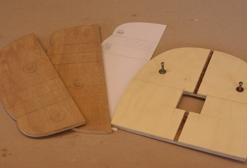
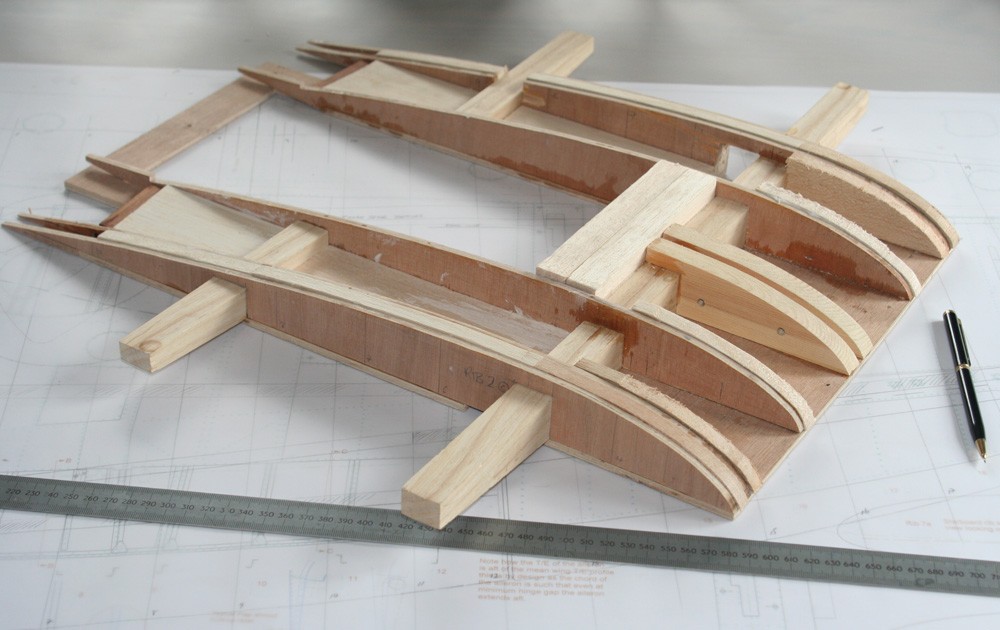
If the plan sounded tenuous, I took comfort that I could provide one additional and significant source of strength and support around the cockpit area: By including the sweeping wing root fairings integral with all my fuselage cross sections, I could massively increase the structural thickness and integrity over much of the ventral half of the fuselage. What is more, the substantial balsa infill in this area, in addition to defining the wing root fairing geometry at an early stage, would serve as an additional means to lock the fuselage and wing centre section together, over and above the various mechanical fixings that I would provide through spar and bulkheads.
A caveat
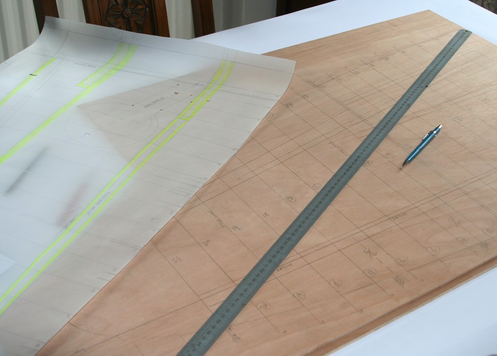
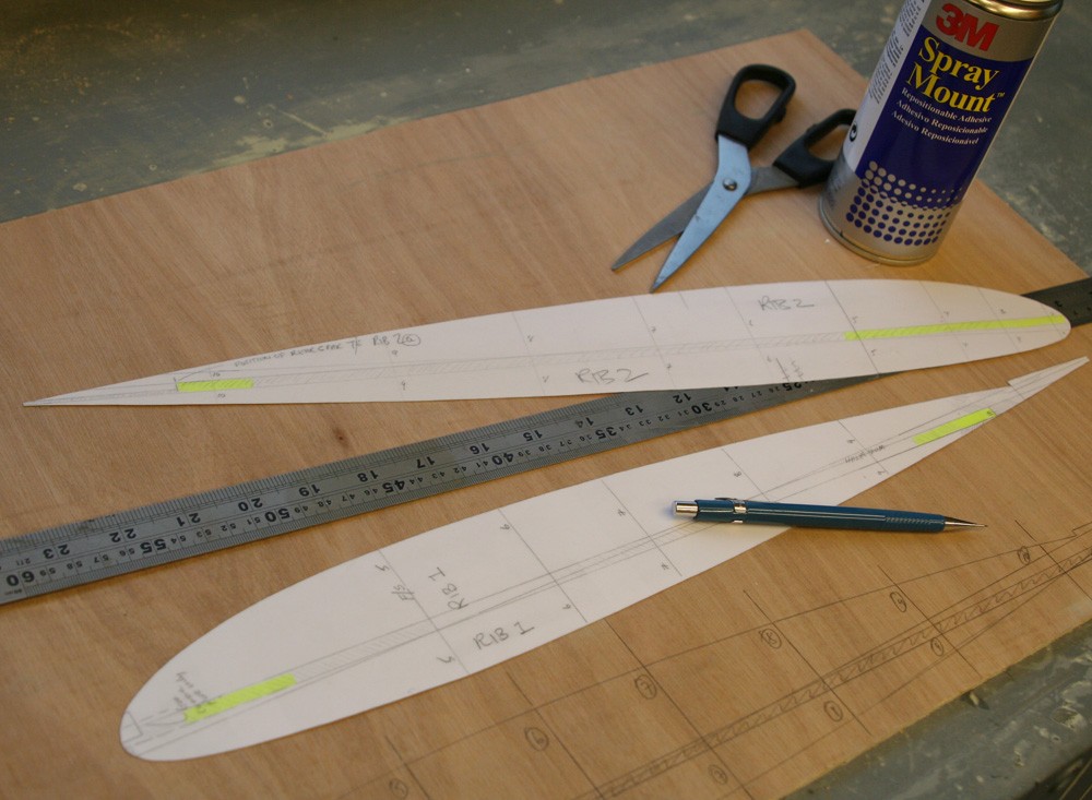
Having come this far by way of ‘thought experiment’ the way was open to begin cutting plywood. But first I needed to purchase a substantial role of architects’ tracing paper by which to transfer the Monforton drawings, and herein lies a cautionary tale: My workshop in March tends to be damp, so I deliberately undertook all the drafting stages in the warmth and comfort of our thatched cottage, monopolising the dining room table for a period of several weeks. I then upgraded the many tracings to template status by pasting them to a lightweight card substrate. But the point of this caveat is to beware of damp! Any template left in my workshop overnight would wrinkle and buckle alarmingly as a result of differential expansion between the tracing paper and card, and when one morning I checked the much larger tracing of the entire fuselage profile I found to my considerable alarm that it had expanded by no less than two to three mm! I assume the tracing paper I used to be paper based; in hindsight I would probably have been better to have used the heavier polymer-based materials which are available. Although doubtless more costly, these surely would be less prone to such distortion. You live and learn!