First cuts
Thursday, 5th September, 2013
I described in my last blog some of the thought processes underpinning the fundamental structural characteristics of the model, and included pictures of the very early stages of the build. Most of March and April was devoted to cutting ply cross sections and preliminary assembly of the front and rear fuselage modules and the wing centre section, at least to the stage where they could be test fitted.
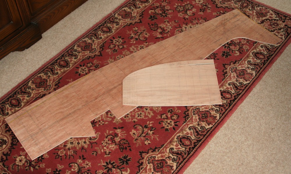
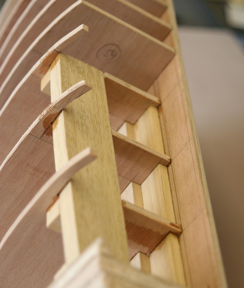
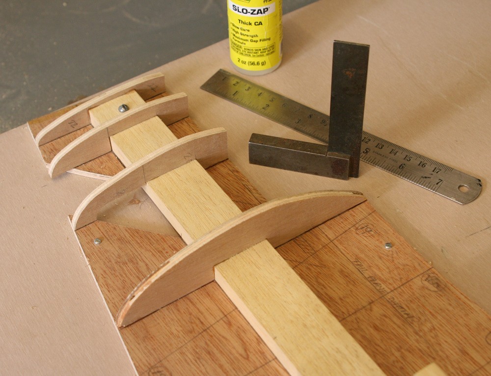
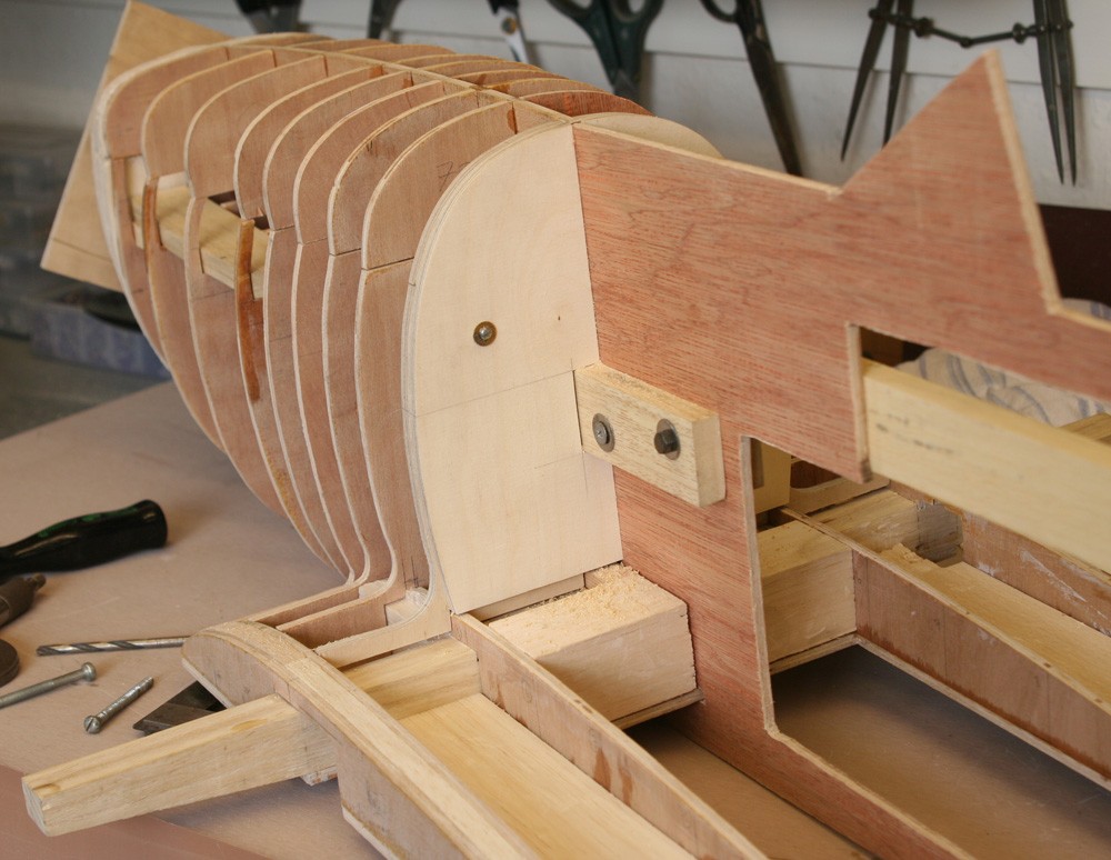
I have mentioned the methodology: The fuselage profile is cut from sheet ply and the longitudinal datum and positions of the cross sections are marked onto it accurately. This provides a central, fore-aft web onto which the rest of the structure is added. The fuselage cross sections are also marked with the datum then cut in two halves, allowing for the thickness of the web, and glued into position, first on one side and then the other.
It is important at the outset that the job is securely pinned to a true flat surface or base board and that most of the stations have been at least partly if not completely in-filled with balsa before the reverse side is tackled. That way there is minimum chance of warping. The wings and tail plane are built-up in the same way, except that here the central web is taken from the plan view.
The beauty of this approach is that so long as the profiles and cross sections are marked out and cut carefully and that the excess balsa infill is carved back and sanded precisely to the plywood edges, no more and no less, the resulting three-dimensional form must be accurate. And here I confess to a weakness... I tend to over-engineer, which in this case is manifest in the use of a solid balsa infill, when doubtless I could save money, and some weight, by leaving the interior mostly hollow, and with no adverse effect on strength or rigidity.
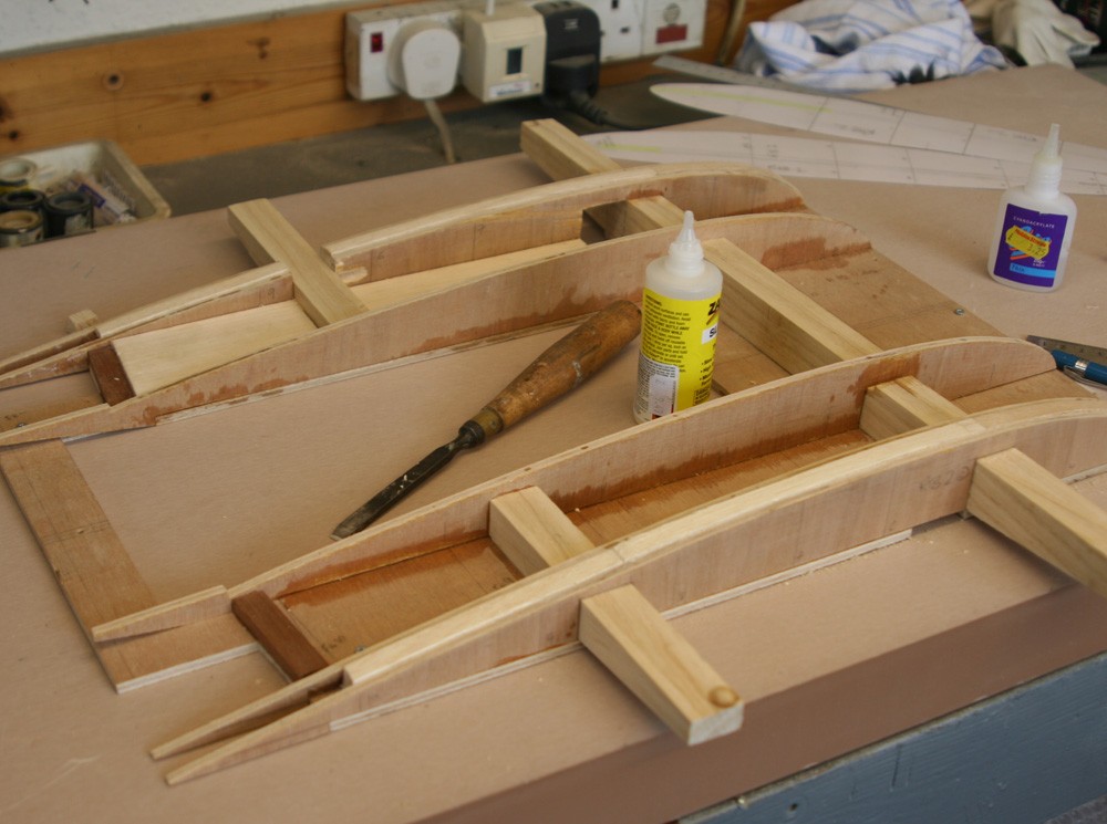
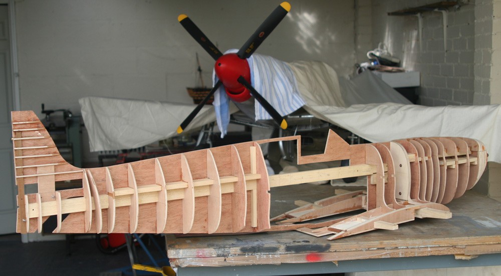
I hope my pictures speak for themselves of progress at this opening stage. While I had an overall strategy in mind, much of its execution tended to be ad hoc, not least the devices employed to hold the main sub assemblies together, a process that inevitably resulted in wasted endeavour and several redundant screw or bolt holes.
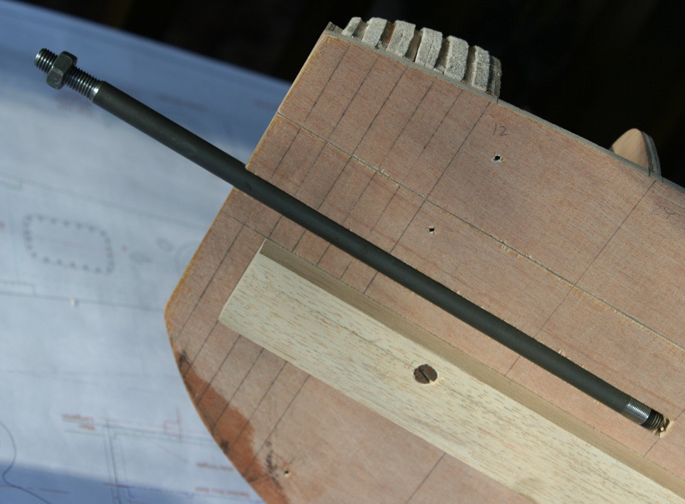
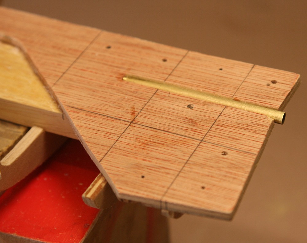
One crucial consideration, however, was that this rudimentary structure foresaw and incorporated provision for all the model’s subsequent features, including undercarriage and tail wheel location and support, positions and installation of prop shaft and exhaust stacks, rudder hinge locations and even the position of the radio mast. This formed part of the preliminary planning process, during which Paul Monforton’s drafts and my own ‘engineering’ modifications became melded into one single tracing, a process which requires considerable forethought and which cannot be rushed.
Over the years I have put together a fairly well-equipped workshop, but at this stage it was only my trusty German-built Proxxon scroll-saw that worked overtime. It has proven invaluable now over two major projects, cutting seemingly endless plywood sections quickly and accurately, something that would be next to totally impractical with a hand saw. With its help, the early stages of the fuselage and nose sections were straightforward, simply a matter of cutting and assembling the sections using a combination of viscous cyanoacrylate for the ply and Aliphatic glue for the balsa infill. Things would become a little more complicated when it came to those sections corresponding to the fuselage frames visible in the cockpit, but more of that later.
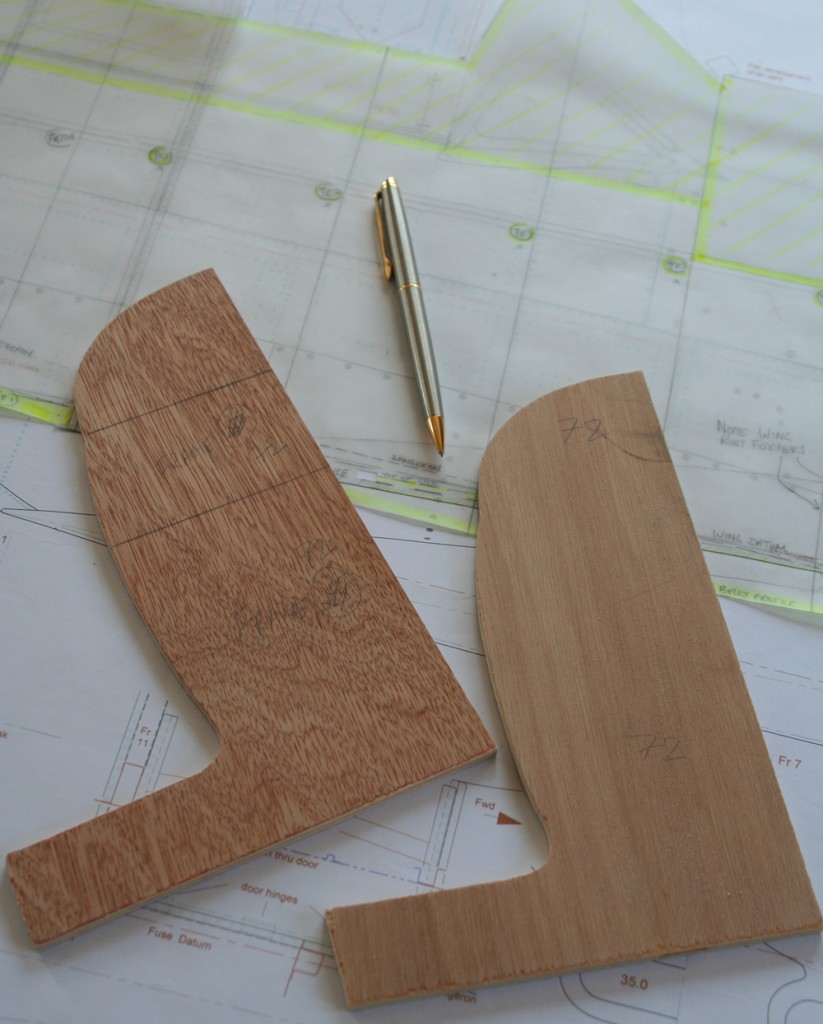
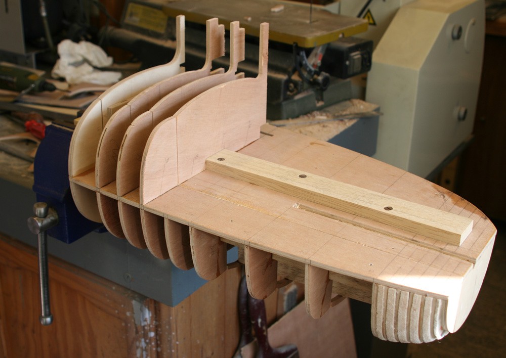
While I cut the plywood plan-view of the main planes at this stage, they were stored away, and it was only the rectangular dummy centre section, with its attendant wing root profiles 1 and 2, that occupied me. I designed the centre section to slot into the nose section, with retaining bolts through the ash spar. As the pictures show, all of the mid-line aft of this was cut away to allow space for the fuselage.
The spar itself is concealed just forward of Frame 7 and I made two further stub spars at around the location of fuselage Frame 10. These hard wood additions separately and variously contributed to structural strength, provided a solid mounting for the undercarriage and the means by which to bolt both the nose assembly and the outer main planes to the centre section.
But all this would happen only after I had boxed the main fuselage sub-assembly together, and this involved installing longerons and skin below waist level to bridge the gap between Frames 7 and 12. Before that could be done I needed to build and detail the firewall along with all six fuselage frames that would be visible from within the cockpit.
Looking even further ahead, much of the internal structure occupying the belly of the cockpit would have to be made and installed while the fuselage was still open and accessible on all sides and from below. Clearly, it would be some time before I would be able to finally bolt together the basic structural elements of the model that were taking shape on my bench.