Switch boxes and buttons
Thursday, 21st May, 2015
A conspicuous feature in the Spitfire Mk IX cockpit is the switch box cluster located low down on the port side just below and forward of the main fuse box tray and extending into the gap between the rudder and elevator trimmer wheels. I had started work on this during the late summer of 2014, and it was not until now that I could summon the zeal to complete this rather testing and intricate part of the cockpit.
The precise arrangement and functionality of the group varies between individual aircraft. As represented in Paul Montforton’s book by some beautifully clear photos of the interior of Spitfire 12-HFL, it includes controls for the fuel transfer pumps, radiator flaps and pitot heat, and a set of guarded push buttons to test the undercarriage warning horn and various other systems.
The most obvious feature is that all the switch plates – and there are eight in total - are canted at a roughly equivalent angle to make them easy for the pilot to reach. Three of the six are stacked neatly one above the other, and it was this that dictated my methodology.
The full-size switches are mounted on individual brackets, each one folded from sheet metal and with integral flanges for attachment to the fuselage skin. I quickly discarded this approach as impractical, not least because of the precise vertical and horizontal alignment required when installing the finished assemblies in a tightly confined space. Instead, and since they are seen only from above, I decided to make most of them in the solid from scraps of leftover resin, thereby side-stepping some potentially tedious sheet metal ‘origami’ and also combing three items into one prior to installation.
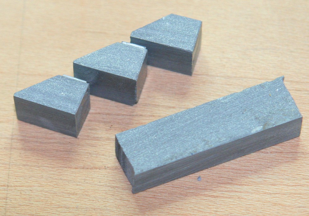
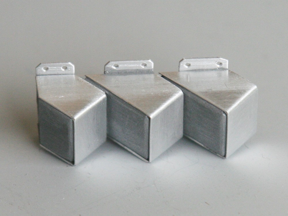
I started with the vertical stack of three, and my pictures illustrate the route taken in milling and gluing together the wedge-shaped resin blanks. To make good the deception I faced the front and sides of each one with folded litho plate, and added three further litho plate rectangles to the rear to represent flanges. Note the rounded off corners of the tiny resin blocks enhance the impression (when painted) of folded sheet metal.
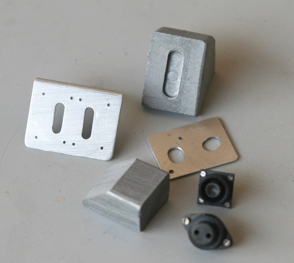
Detailing the two adjacent and larger assemblies presented its own challenges, but, as can be seen, the underlying supports were made in much the same way as described above, including their dummy flanges.
When it came to the triple toggle switches located between the trim tab controls I changed tack completely, making the support tray from litho-plate, more or less as specified in the production drawing – its geometry requiring only three parallel folds.
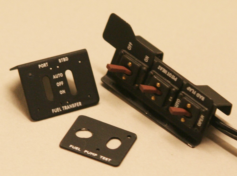
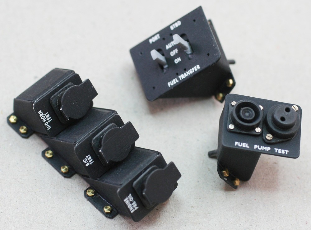
So far, I have focussed on the support brackets for the cluster. Yet before I could add the controls themselves, they all required individual faceplates, which, in turn, required a set of rubdowns for the labelling (Notes on making rubdowns are given elsewhere on this website).
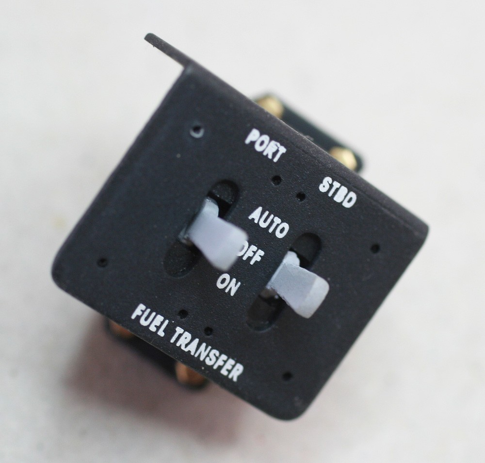
Finally came the electrical components themselves. I made the three in-line toggle switches and the paired fuel transfer switches by casting and assembling additional resin copies as described on my diary page of July 30. The single visible push button and its collar and the accompanying electrical connector were easily turned on the lathe from hard black plastic – although the subsequent drilling of these tiny parts and the addition of minute brass screws took patience, to say the least!
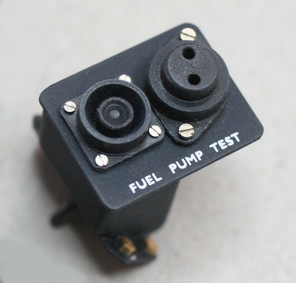
Fortunately, I was spared this when it came to the bank of three vertically-stacked test switch buttons, since all are concealed under flip-up lids which, in the real aircraft, shield them from accidental use. Nonetheless, the switches are each represented by three tiny pieces: a square base and cylindrical body, both made from black styrene, and a lid cut and files from litho-plate… a fiddly job indeed!