The instrument panel
Friday, 5th June, 2015
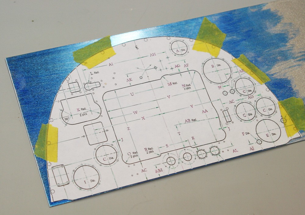
Cutting out the instrument panel is a straightforward task, prompted at this stage in order to verify the accuracy of its fit against the upper cockpit sidewalls.
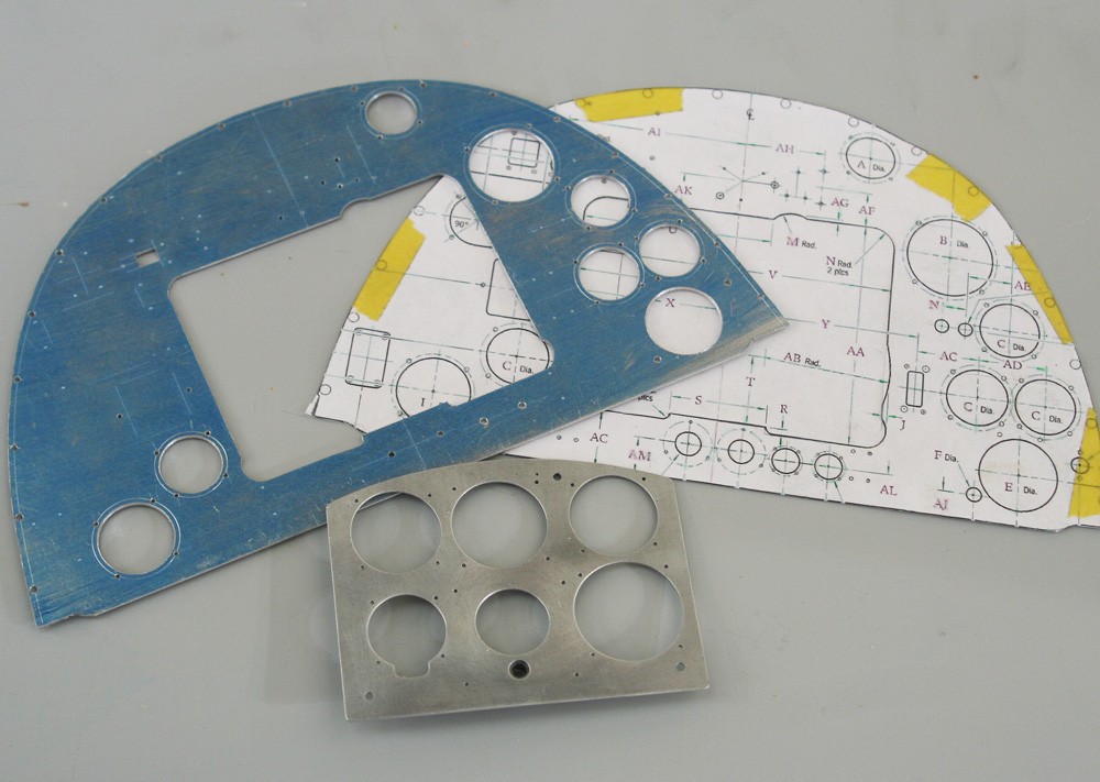
Having marked out the component positions, including all screw holes (of which there are many), I cut the rectangular blind flying panel from 0.5 mm aluminium sheet, stepping up to 1.0 mm material for the main panel.
Cutting the numerous apertures for the instruments takes time. With the exception of making pilot holes, I avoid using power tools on thin aluminium because of the risk of judder; instead I open up each hole close to final size with a series of round files and finish off with a reamer.
Not all the apertures on the full sized panel are necessary in the model, for example some of the switch clusters and the large rectangular oxygen regulator can be made and fitted directly to the front of the panel, and no one is the wiser.
The blind panel stands slightly proud, and in the real aircraft it is attached by three rather novel mounting brackets that serve to dampen vibration – two at the bottom and one at the top. Needless to say, I simplified this by using three tiny rectangular back-plates with cylindrical spacers to achieve the correct relief. The back-plates are attached to the main panel by scale screw clusters (14BA) as denoted in the drawings and three rather prominent 12BA bolts pass through the spacers to hold blind flying panel.
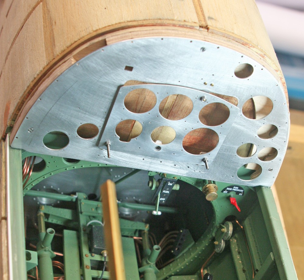
In the full-size aircraft the entire panel assembly is secured to the airframe by no fewer than 17 screws pitched evenly around its periphery. In my model this is impractical because of the extreme closeness of the holes to the edge of the underlying plywood supports on which it sits. While I could easily represent the 17 screws with dummies, the real attachment points would have to be relocated.
This is not as simple as it might seem and for the following reasons: Firstly, I needed to use relatively large, out-of-scale fixings – at least 10BA – so as to be confident of repeated installation and de-mounting of the panel during construction. These screws – and I would need at least three – would have to engage in ‘captive’ nuts embedded in the ply support, and they would have to be hidden from view.
I puzzled over this and finally came up with a compromise: The first screw would locate at the very top-centre of the panel, where it would be effectively hidden by the gun sight; at the lower left I secreted one in the space behind the rectangular magneto switch plate; and at the lower right I made the small aperture for the fuel pressure warning light double as my screw hole, since the light fighting itself could be emplaced over it.
My photograph shows the bare panel installed, and the good news is that the fit with the upper sidewalls is good, even to the requisite tiny gap around the circumference. Fitting the panel out must come later.