Control column - Part 1
Tuesday, 9th June, 2015
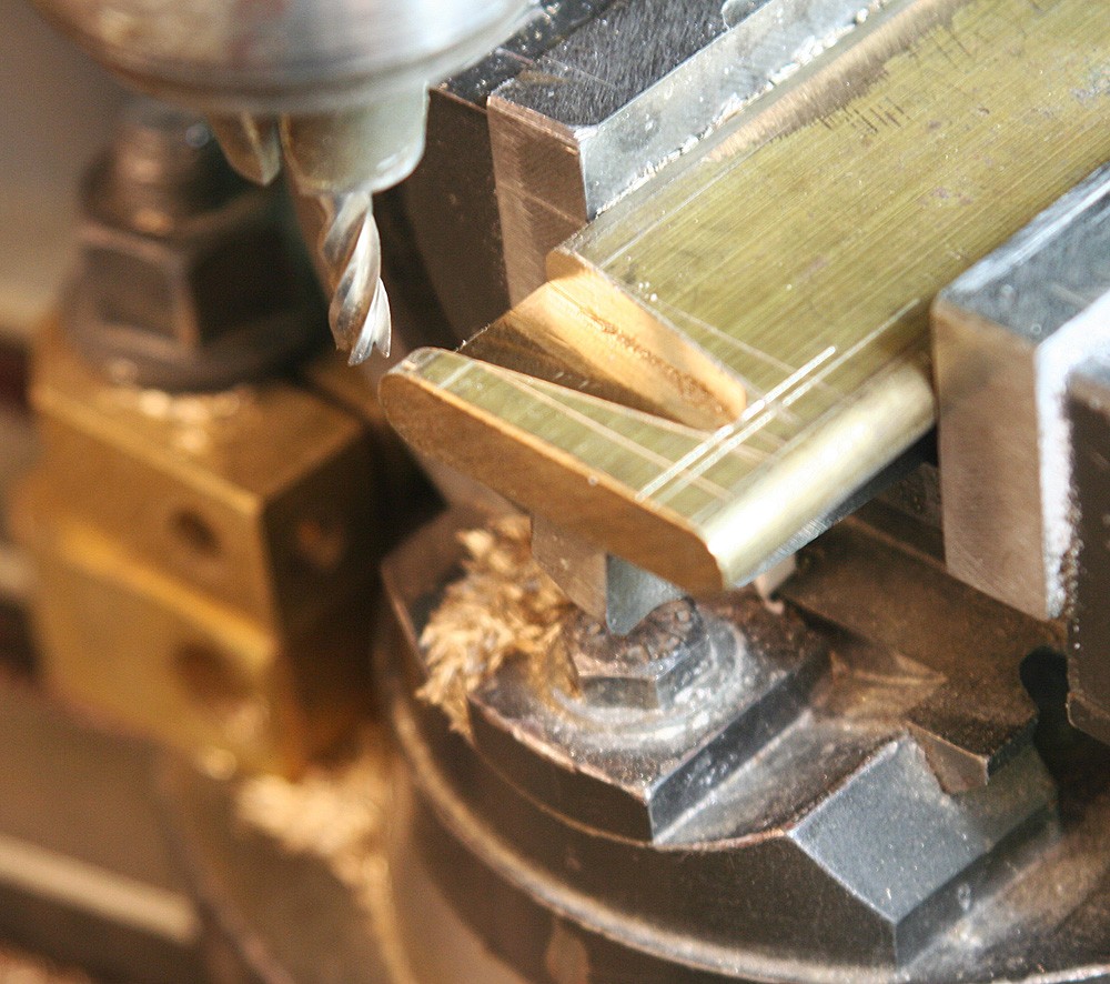
The finished control column represents a week’s work. I built it from the top down, starting with the wedge-shaped pivoting neck that carries the spade grip.
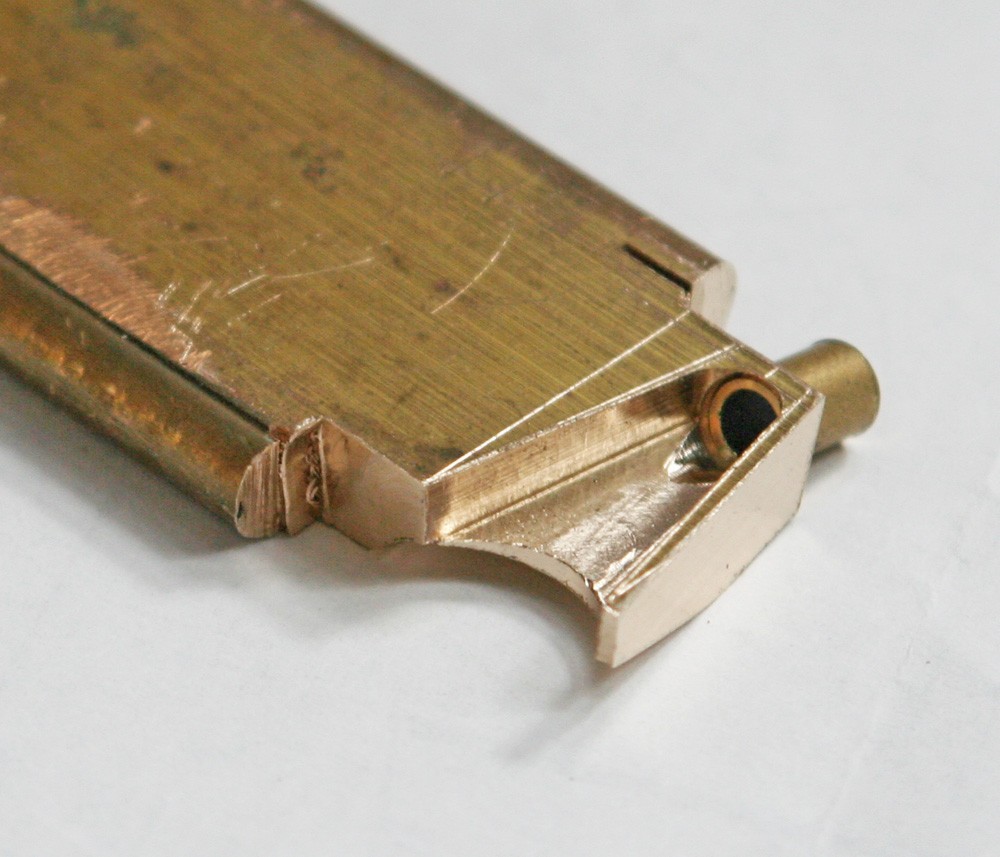
The hard part was getting my head around the geometry, since the neck offsets the spade grip forward and parallel to the column itself. As my photos show, it is milled from solid brass and drilled at the top for a stubby tubular boss. A half-circle is cut into the base of the wedge to take a turned brass disc, which is soldered in place, effectively completing the rear of the piece. The disc is drilled centrally for the pivot bolt and peripherally for a set of dummy countersunk screws.
The Dunlop spade grip fitted to the Mk IX Spitfire is distinctly and inconveniently oval, so I made a former by milling two flats onto an off-cut of solid round brass. I used 11/64-in. brass bar for the grip, cut long to allow for leverage and annealed thoroughly to soften it. With the former held securely in the vice, I was able to bend the rod around it like a garrotte until I had achieved a tight circle. The opposing ends – having performed their function as levers – are cut to waste and the circle pinched or hammered flat.
With the work repositioned on the former, the two straight sides can be created, by pinching gently in the vice. Predictably, this causes opposing bulges perpendicular to the pressure, but these can be re-dressed to shape by alternate squeezing in the vice jaws and gentle hammering on the anvil. The job proved easier than anticipated, since it took only two attempts to get it about right!
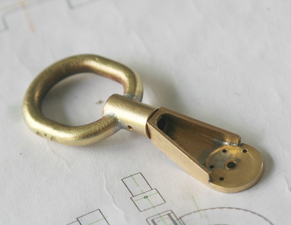
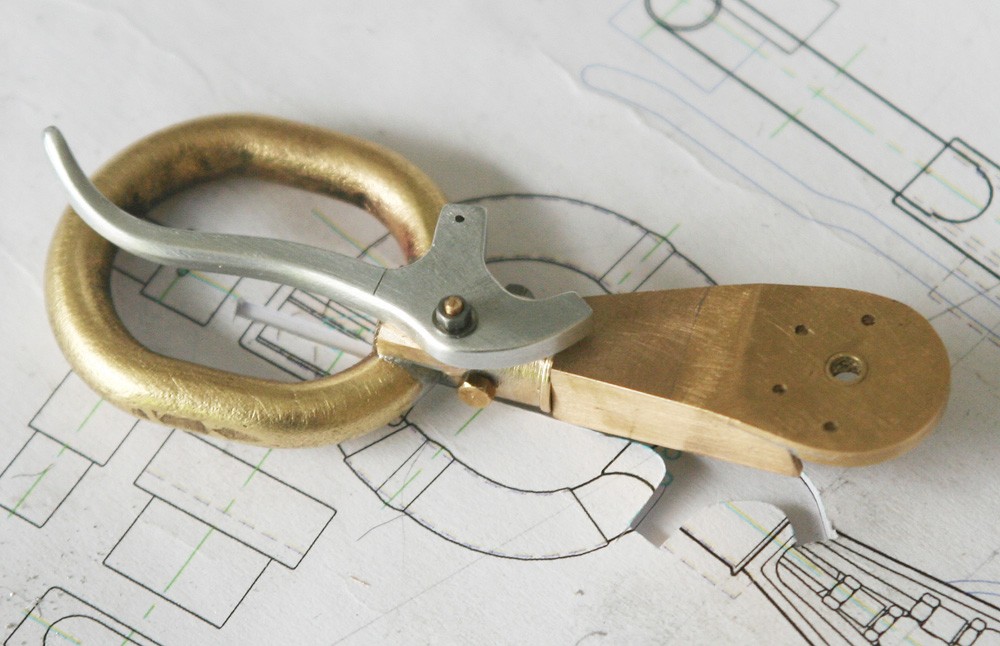
Photo 3 shows how the spade grip is soldered into its turned brass mount. The latter is double-bolted to the neckpiece, and in the picture one of the two holes has already been drilled.
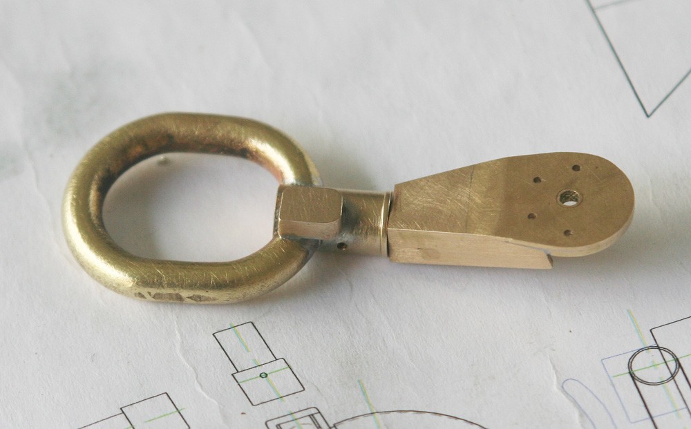
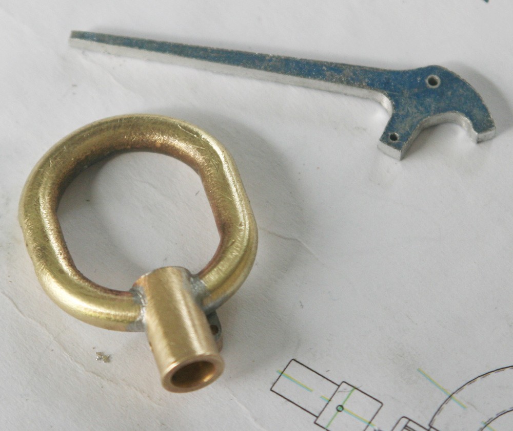
In Photo 4 a small rectangular brass pad has been soldered to the rear of the assembly, and this carries the brake leaver. The lever itself is cut overly long from 3/32-in. sheet aluminium, then dressed to shape with a file followed by gentle bending in two planes to set the graceful curvature. The smooth sheen is achieved with steel wool.
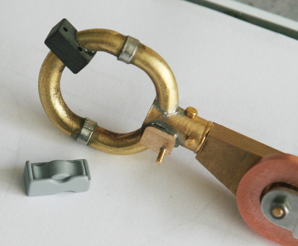
The simple ferrules seen either side of the spade grip were simulated with strips of pewter shim glued on; the gun button assembly with its rocker switch were less straightforward.
I made the rear electrical housing from some hard black plastic material I had I stock, milling a deep channel in it at the required angle to accept the spade grip and drilling two holes for the electrical wiring. This took three goes to get right! The larger rocker switch housing is made up from sheet styrene – in effect, a tiny open box with sides of unequal depth. Finally, the rocker switch is milled and carved from a scrap of casting resin left over from previous jobs. I often use this material for such work because it machines and cuts so beautifully. The domed centre of this switch should be knurled – a detail that unashamedly I have omitted!
I still need to simulate the crinkly coating with which the grip is sheathed, but this will be a job for the post-painting stage.