Control column - Part 2
Sunday, 21st June, 2015
With the spade grip assembly complete, the next task is the column itself, beginning with the forked housing at the top. It is sometimes easier to machine jobs like this from hexagon bar, where the flat sides help as a guide when milling and cross drilling. Hexagon is also easier to grip in the machine vice than round bar.
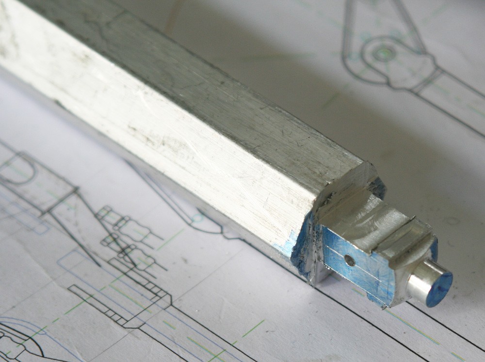
The first operation is to lathe-turn the throat of the forked housing, making it a push fit into the top of the column. The work is then transferred to the mini-mill, where Photos 1 and 2 give an idea of the sequence of facing, slotting and drilling. The final stage, which involves forming the radius at the top is done by hand with the aid of a simple lathe-turned filing guide (Photo 2). The housing is held in the column by two 1/32-in. alloy rivets.
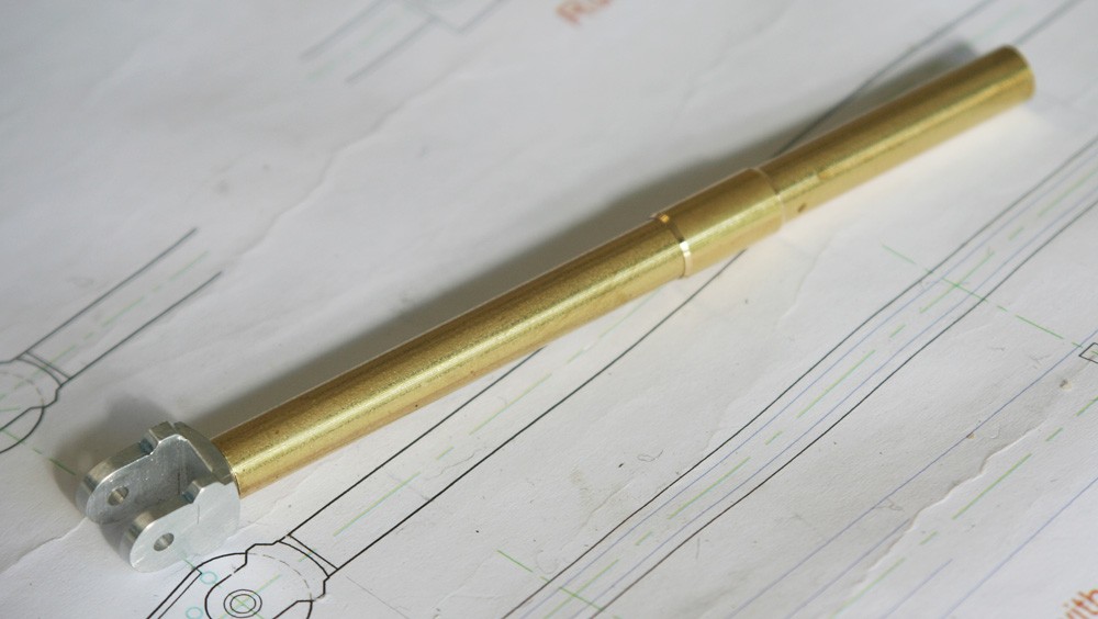
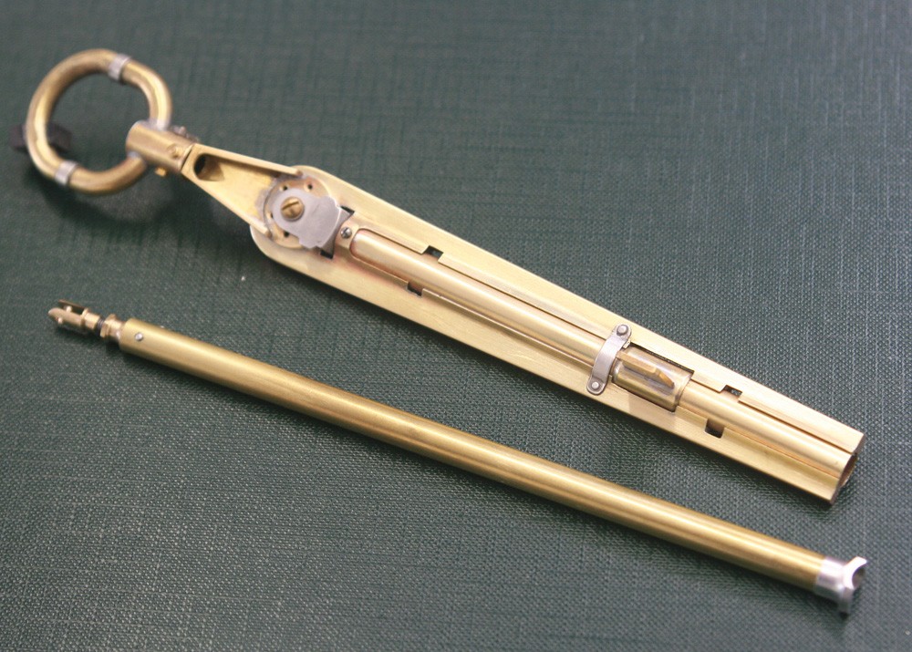
The column itself is thin walled brass tube of /32-in. OD (Photo 3) with a short sleeve near the base to support the lug on which the elevator connecting rod pivots.
In the real aircraft lateral movement on the grip is transmitted through a sprocket wheel to a chain and tie-rods that flank the column. But since all of this is hidden by the tapering chain guard it is of no concern. I used much the same technique as in my first Spitfire, modelling the guard in the solid but making it look like sheet metal.
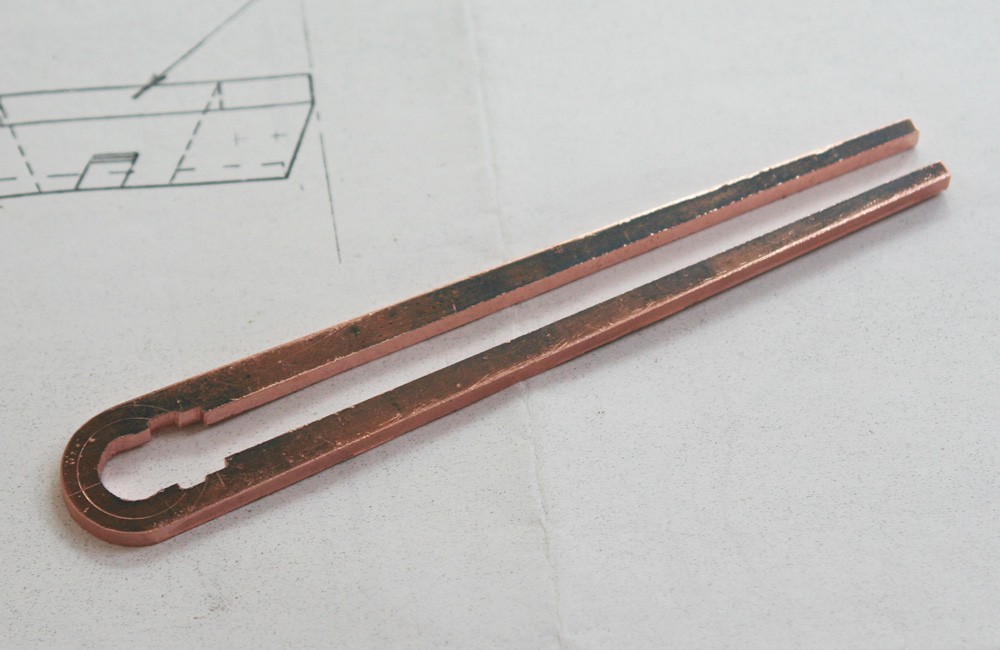
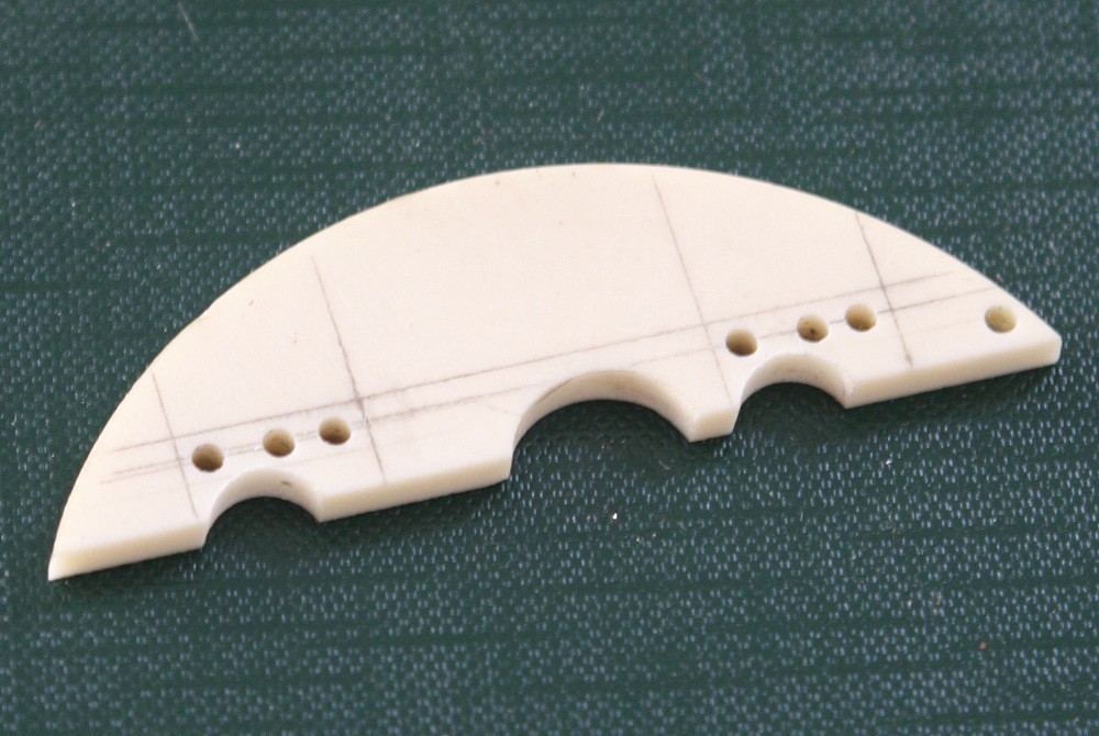
Photos 4 and 5 show the guard cut in the piece from 1/8-in. copper plate and then later after dressing up with 10-thou brass shim. The thin brass is carefully folded to replicate the bevelled inner sides of the real thing, where they nestle up against the tubular column. The brass is notched to accept the pneumatic hose clips, and it incorporates a collar at the top, where the guard is held in place by a single bolt. There is a similar feature at the base of the column, but I ignored this since it is all but invisible when installed.
Soldering on the brass ‘facia’ is tricky, not least due to the risk of re-melting previous work. I left the outer sides of each piece full and ran soft solder generously all the way round from top to bottom. With the left side done the operation is repeated for the right side, then the excess material is cut away (with sharp scissors) and filed flush. Finally the square outer edges are rounded off a file and Emery paper, thereby enhancing the effect of a tooled sheet metal pressing.
Detailing the column
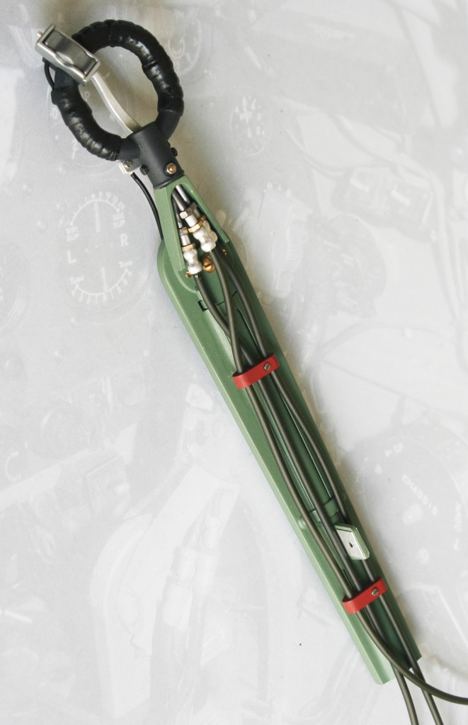
Essentially, this involves adding the rubbery sleeve that sheathes the handgrip plus a pair of three-station hose grips (Photos 7 and 8).
The first stage is to whip the grip with fine thread (the stuff supplied to ship modellers as running rigging). The whipping can be quite rough and irregular, with the odd gap left here and there. Next the whipped section is painted with ultra thick plastic modelling enamel. The Revell brand is ideal since unused paint invariably thickens in the tin. Several filling coats are applied until the identity of the underlying thread is lost leaving a smooth but crinkly surface. Finally this is painted a slightly darker shade of dark grey using gloss paint with a touch of matting agent. The result is realistic, especially if it retains slightly higher sheen that the grip itself.
Photo 6 shows the method for the hose clips, and once again the raw material is scrap casting resin. The tiny blocks are drilled first, then shaped, and sprayed. Once in place on the column, tiny pieces of pewter sheet are glued on either side to simulate garter-like retaining straps, with a single countersunk screw on the front.
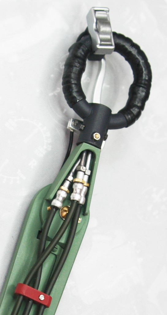
Pneumatic hoses
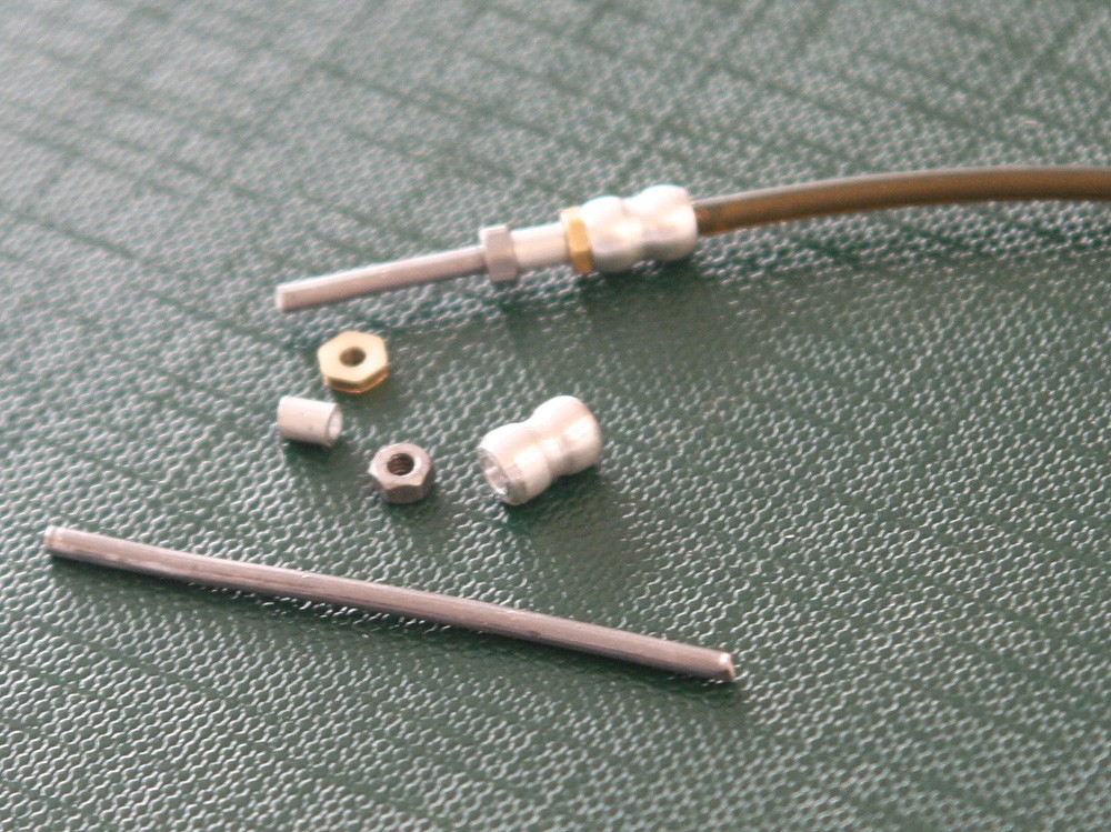
Three pneumatic hoses emerge from the neck of the spade grip, and these can be replicated beautifully using silicone rubber tube of the kind available in fishing tackle shops. Short lengths of soft solder are perfect for the upper part of the line runs. The hose couplings are a different matter, each one a composite of four tiny pieces: two hexagon ‘nuts’, a short length of aluminium tube and the hour-glass shaped connector which has to be turned on the lathe (Photo 10). Assembly involves threading each piece in sequence onto the solder before bonding them in place with tiny applications of ultra thin cyanoacrylate, which gets sucked straight in. The silicone rubber hose fits into the lower half of the ‘hour-glass’ and is held by a dab of viscous glue. All in all, it’s a tedious operation, and especially when done twice; I made the first set too big!
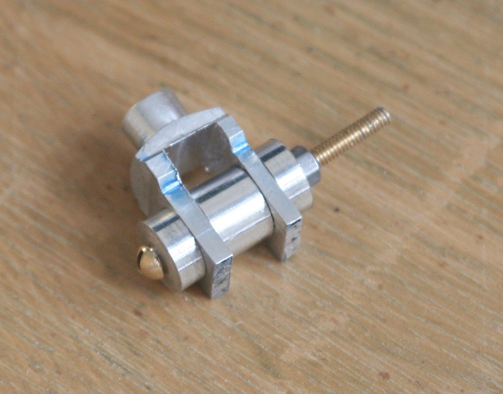
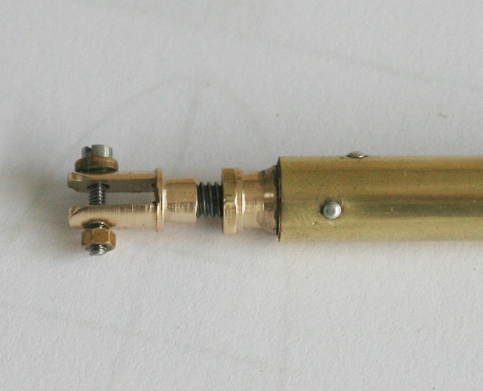
Elevator connecting rod
This is simply a length of 1/4-in brass tube with an aluminium 'stop' machined to slip over the aftermost end (Photo 5). The forked coupling is turned in the lathe, cross drilled and slit in the milling machine, then made up using a turned brass plug and a locking nut threaded on a short length of steel screw studding, as shown in Photo 9.