Fitting out the instrument panel
Sunday, 27th December, 2015
If my woeful four-month long neglect of my diary has been noticed, then in mitigation I can at least claim to have been busy on the model! So on this Christmas 2015 it is time to take a break from the workshop and pick up the thread again before my recall fails me.
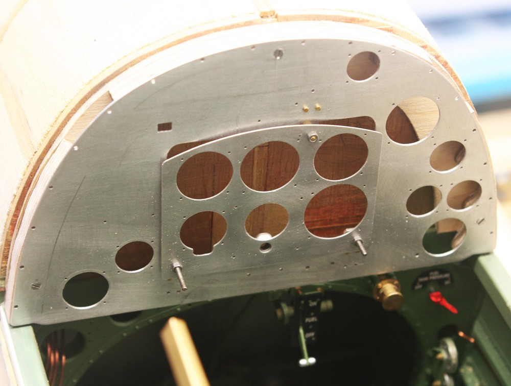
Back in August I described fitting out the upper cockpit sidewalls, yet their permanent installation – a long anticipated milestone for the model – still awaited completion of the all-important instrument panel.
The basic sheet metal work was done in the Spring of the year (see diary entry of June 5), yet on dusting off the parts and revisiting the drawing I awoke to a subtle but discomforting error: My blind flying panel, cut from 12 thou litho pate, was too thin! I was tempted to let it go, but at the last minute discipline prevailed and I cut a second version from 0.5 mm alloy. Strictly, the main panel – currently 0.5 mm – should have been commensurately thicker, but I let this go since with the panel fitted this error would be hidden.
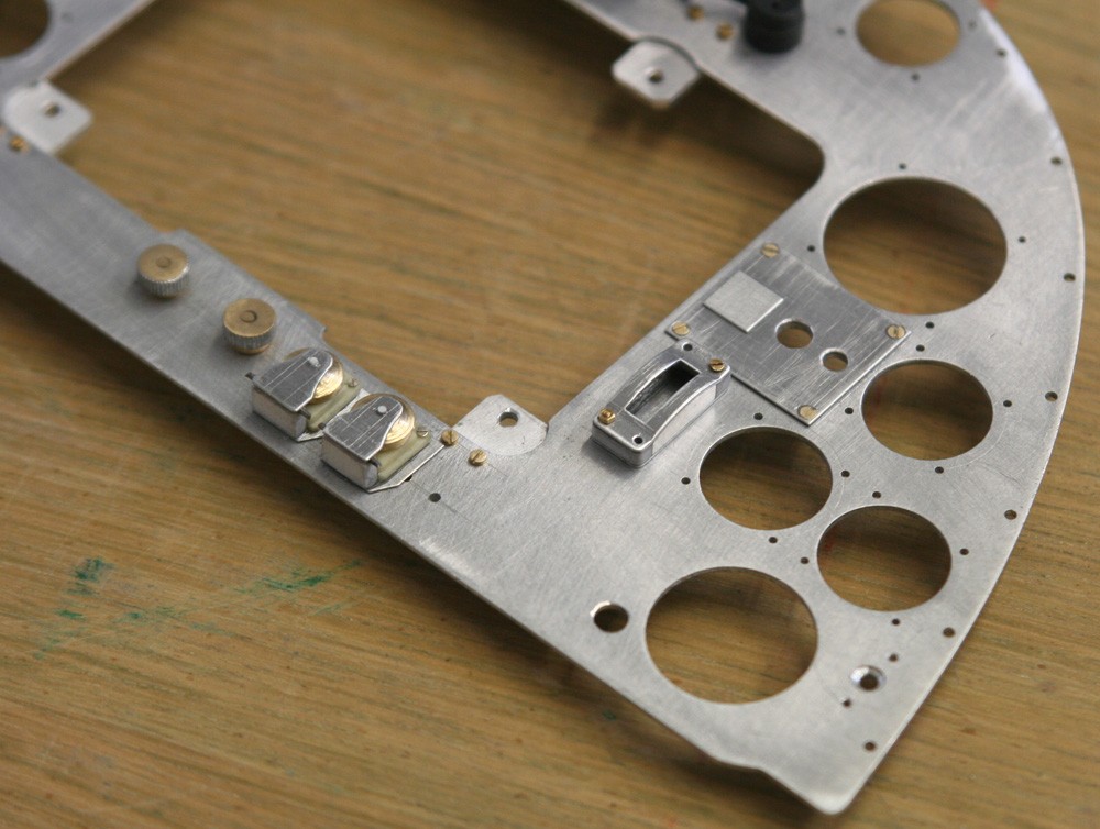
As always in scratch building there is the need to think ahead. In the full-sized aircraft the main panel is secured to the airframe by a series of peripheral round head screws equidistantly pitched. Since this is impracticable in the model (these sale fasteners all being dummies), I needed to devise a way of hiding three grossly over-scale countersunk screws. By locating one at the top of the panel this is easily achieved; but the other two are more problematic. I solved the conundrum by placing one behind the small magneto switch plate on the port side, and the other behind a warning light assembly to starboard. Thus when the time came the panel could be installed complete except for these two elements, which were both designed with locating pins to facilitate gluing in place as the final step.
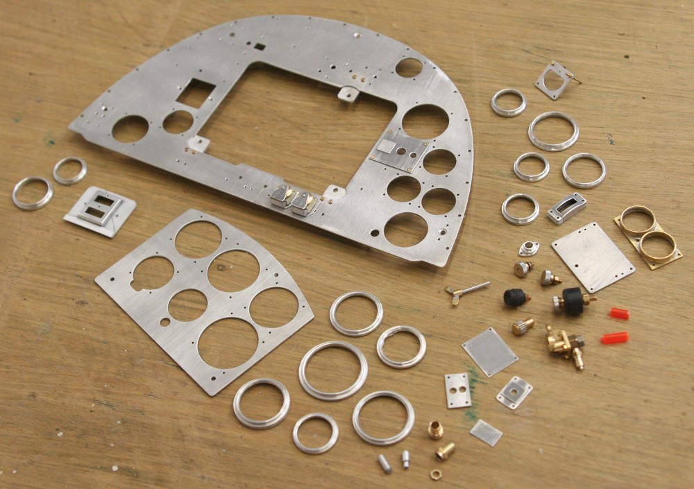
My pictures illustrate this point and also the extent and variety of the work required to fit out the two panels, including numerous bezels, typically lathe-turned from various diameters of thick-walled aluminium tube or solid bar. The job appears daunting, yet it is surprising how quickly a neat bezel can be produced and parted off, so long as care is taken to avoid ‘remakes’!
I was tempted to say that collectively the bezels occupy the major part of the fitting out, but this is not so, since items such as the chassis up-down indicator, flap operating lever, oxygen control sub-assembly and oil pressure indicator, while fewer in number, are more challenging and together take more time and innovation; moreover, not all are fabricated using the same techniques employed in my Mk I Spitfire.
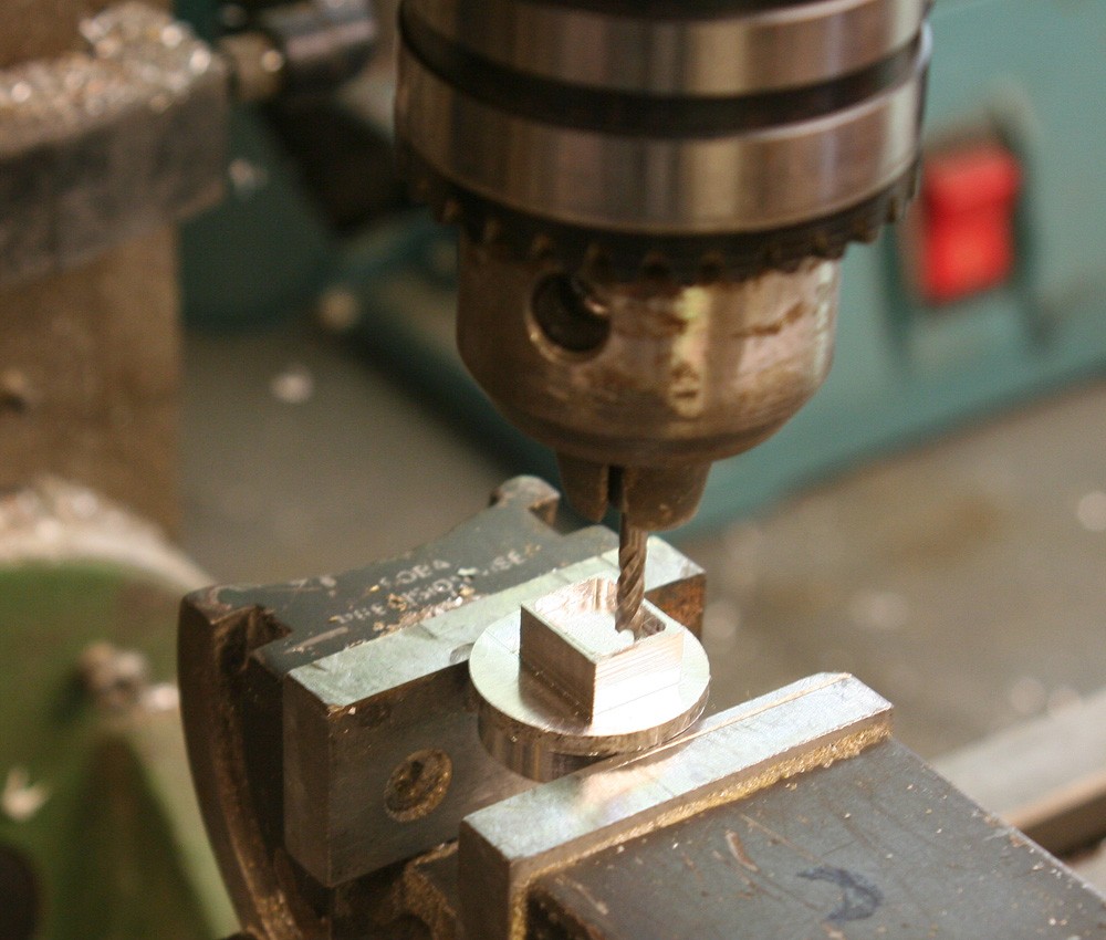
For example, the undercarriage indicator in my earlier model was made from soft soldered brass parts; this time it is milled in one piece from solid aluminium, with the two rectangular windows painstaking opened out and finished with a jeweller’s square file. I’m not sure which gave the better result, but the temptation to explore a new approach, in the face of something that worked in the past, is often hard to resist.
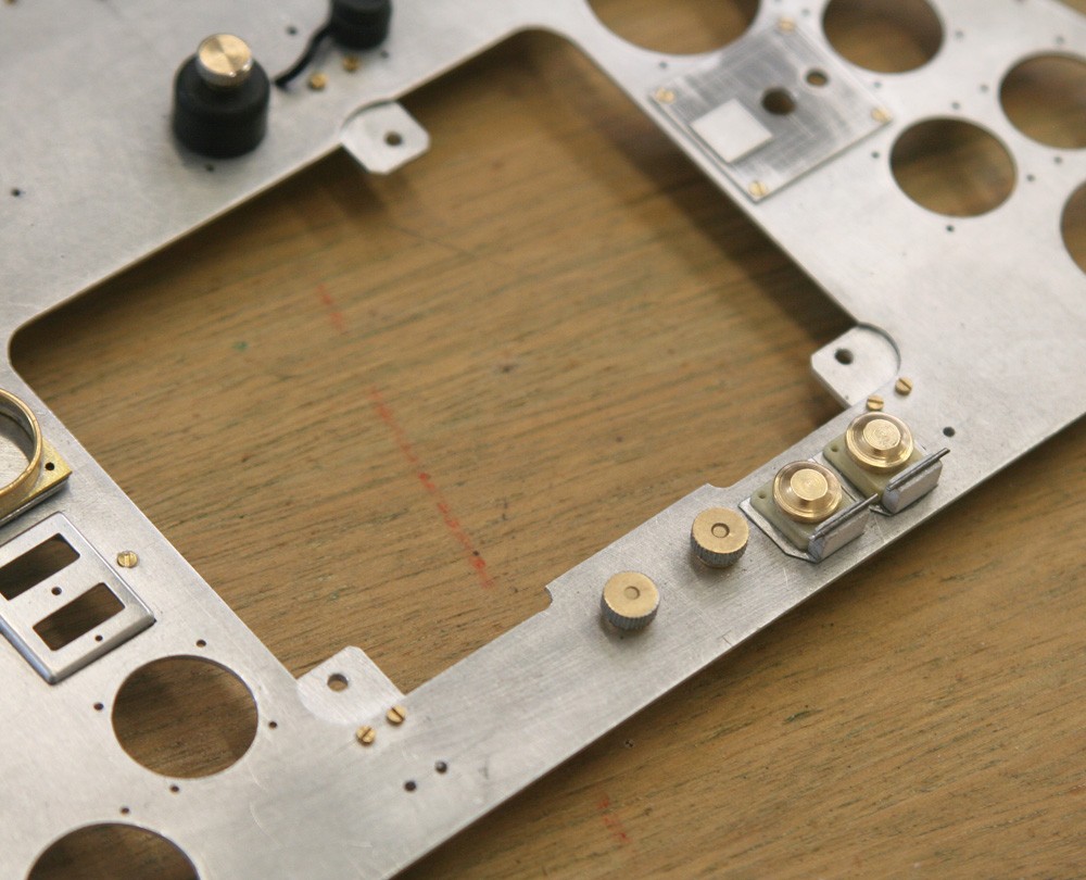
Noteworthy are the engine start and boost buttons at the base of the panel. Shielded by flip-up lids these posed a challenge to model. My pictures highlight the eclectic mix of materials used: The base is litho plate; the squared body is buff-coloured casting resin (from the same mould as the electrical switches). The perpendicular support for the hinge is high-density model board and the hinge itself is piano wire. I turned the hat-shaped shield from brass and cut and filed the tiny bridging plate from litho plate. The result is not a perfect copy, but very close, and the moral is that even challenging items can be scratch built using the ‘reductionist’ principle, which involves mentally breaking down the shape into its most simple component parts.