The Spitfire's side cowls
Tuesday, 5th January, 2016
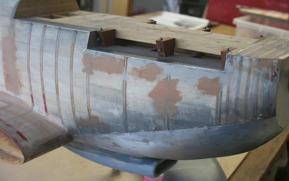
By mid-November I turned to the Spitfire’s side cowls, the easiest of the set in terms of their surface contours.
Work began with some localised repair and fine-tuning of the balsa substrate with wood filler, followed by the grafting on of a litho capping plate in order to give a positive, clean and accurate line to work to where the side and top cowls abut.
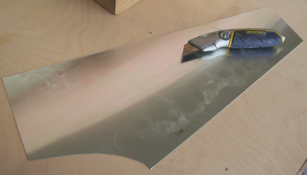
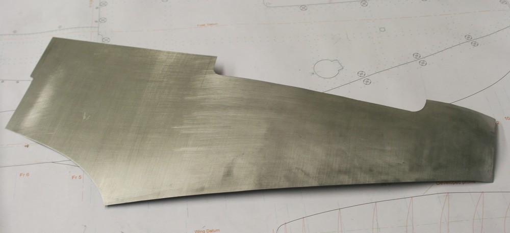
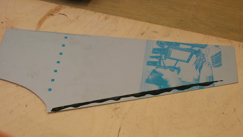
In doing this kind of work I find that the closer the initial litho plate blank is to the finished outline, the easier the metal is to work, so I cut a paper template allowing a cm or so margin all round. Given the relatively gentle curvatures, it would have been convenient to dispense with the annealing stage altogether, but I judged this unadvisable.
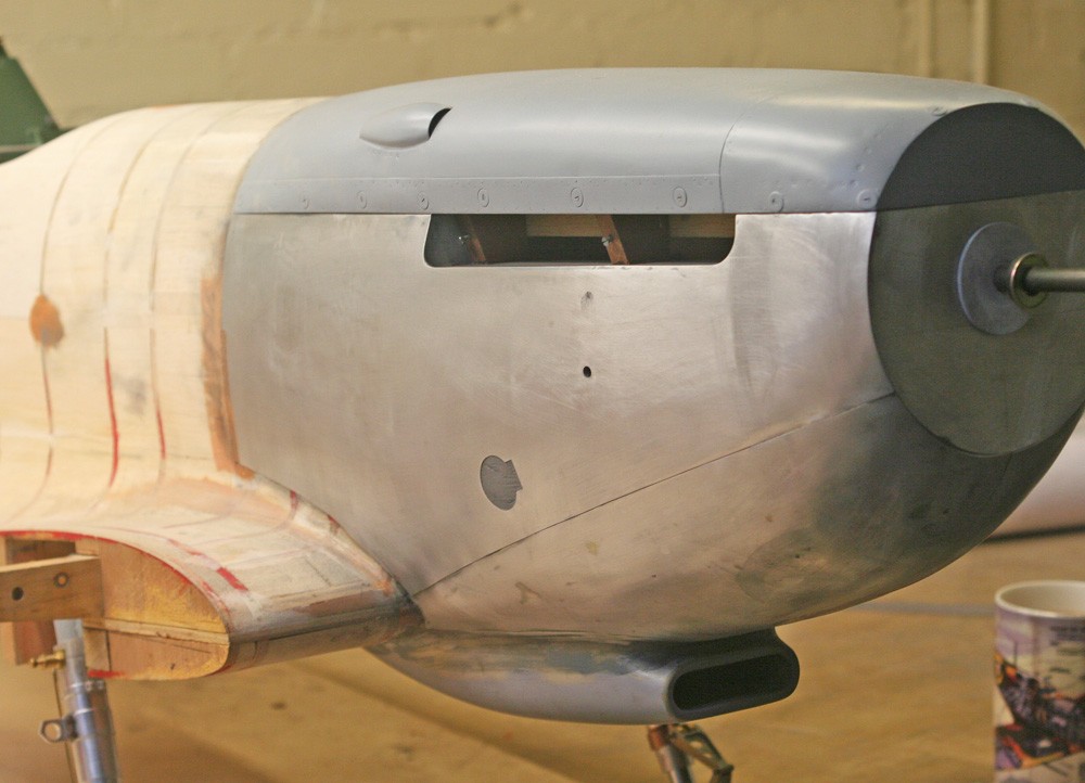
My usual routine is to anneal, work the panel, check, anneal, work again and when relatively happy with the fit to tape the piece to the model on order to scribe the top, front and rear cut lines. At this point the precise relative positions of the various doors and openings – including that for the exhaust stack assembly – can be located and their outlines marked on. Engineer’s blue dye is a great aid to accuracy when cutting skin panels.
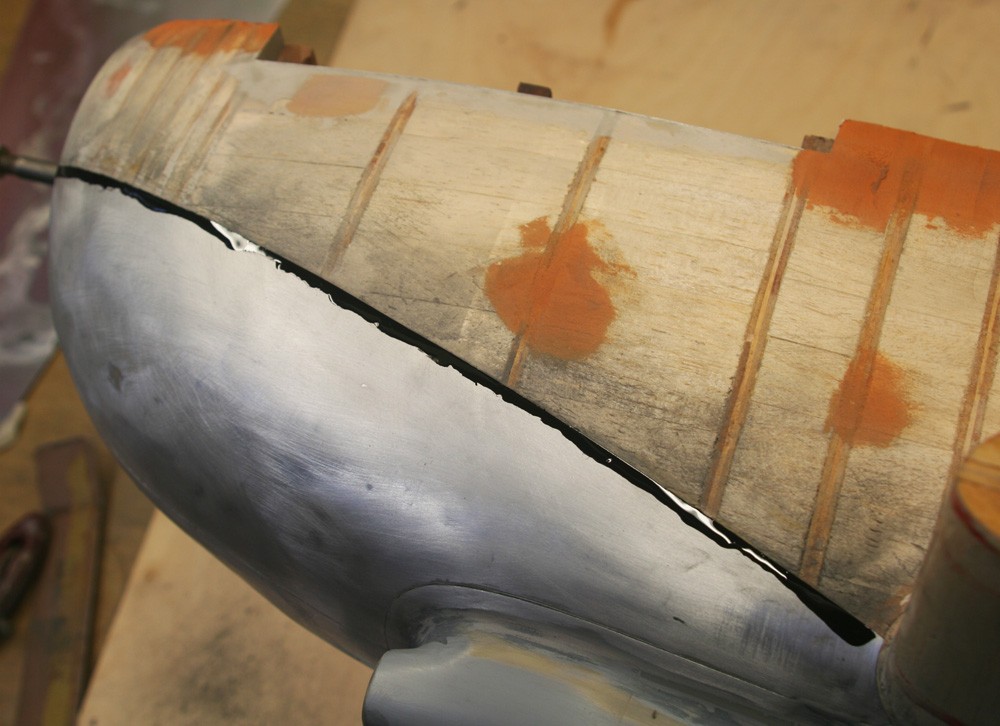
Because it’s impossible to see through litho plate, the final cut where the curved side and lower cowls abut requires extreme care. I do not pretend that my method is ideal, but it’s the only one I know. I have mentioned it previously, and hopefully this time my photographs might help. If anyone knows of a better way, I would be grateful for the advice.
I installed the side cowls using contact adhesive. I can only stress again the vital importance of accurate positioning when emplacing a glued panel glued with EvoStik, for the ‘grab’ is instant and leaves little or no margin for adjustment or correction. I habitually undertake several dry runs before applying glue to be sure to get it right.
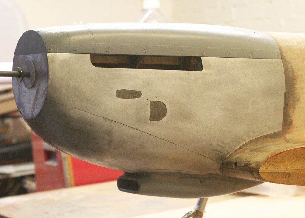
Air intake scoop
The little air scoop that features on the port side cowling is there to supply coolant air to the generator. Items like this, and the similar vent on the top cowl that serves the engine compressor, are far easier to make than they might appear. Here’s how I do it:
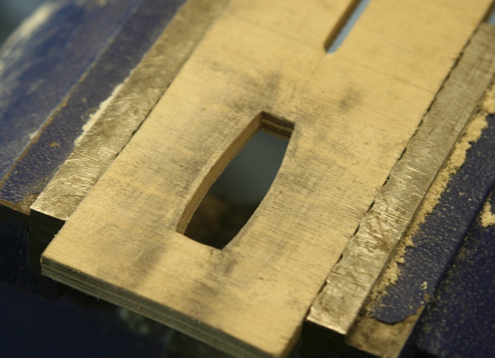
- -Cut the plan view out of a rectangle of quarter-inch ply or similar
- -Cut and anneal a blank of 0.5 mm alloy leaving a generous margin along the top and bottom sides for the flange.
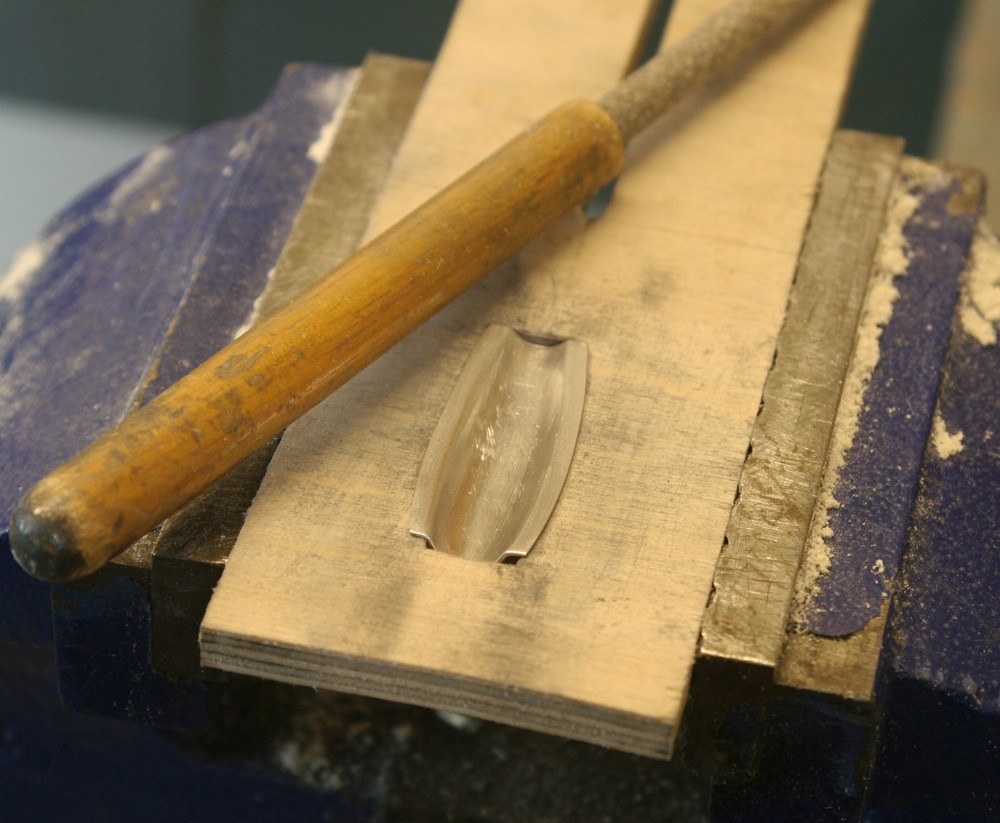
- -Grip the ply former in the bench vice and align the softened work-piece over it.
- -With a suitable hard wood implement, rub away at the metal so as to force it down into the aperture. Re-anneal if needed and continue the process, using various diameters of tool if needed, until the required shape has been achieved.
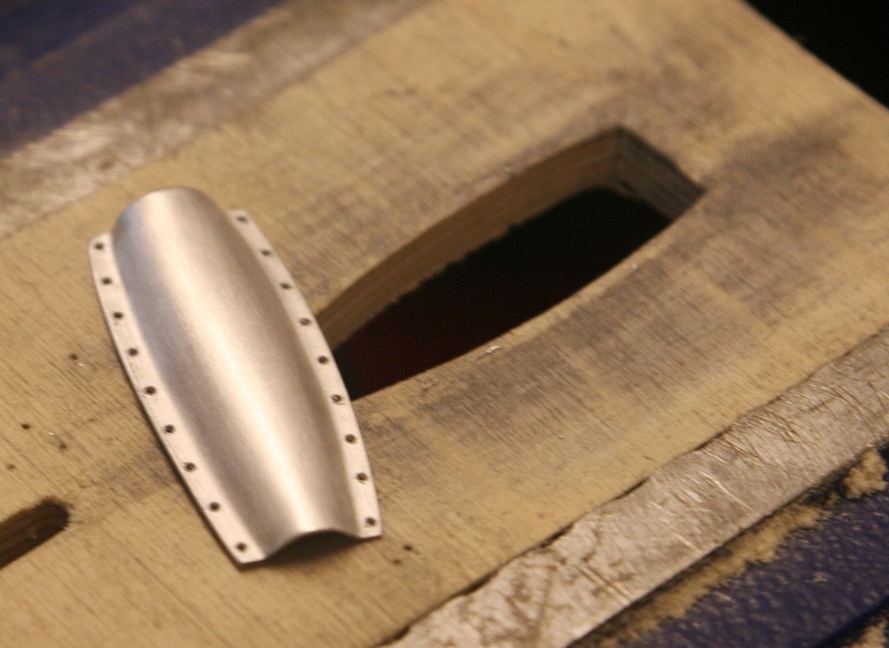
- -Remove the piece, and if all is well cut the flange to shape with sharp scissors.
If there is a complication it is that cowl surface on which the little intake is riveted, is itself curved in a convex plane. Yet this too is easily overcome by sanding an equivalent shallow concave curvature into the surface of the ply former.