The windscreen - Part 1
Saturday, 29th October, 2016
The Spitfire’s windscreen proved a near insuperable challenge. Even before cutting the first metal, I spent weeks pondering the route to take, like a climber struggling to find a toehold. And after each Eureka moment came the realisation of some or other impediment, until I truly began to think the job beyond me. This may seem surprising given my previous experience when building my Mk I Spitfire. But it is important to realise that the two differ in crucial respects: the armoured glass of the Mk IX is on the inside and the glazing arrangement has an extra upper pane. Both make building and fitting the windscreen markedly more challenging.
Overall, the job took six or seven weeks to complete. It occupied all of July and most of August. In retrospect, I am happy with the result, yet something in me says it could have been better. What follows is a brief account in two instalments of this rather taxing stage in the model, beginning here with the forward panel that contains the armoured glass. Each of the paragraphs below refers specifically to one or more of the accompanying photographs:
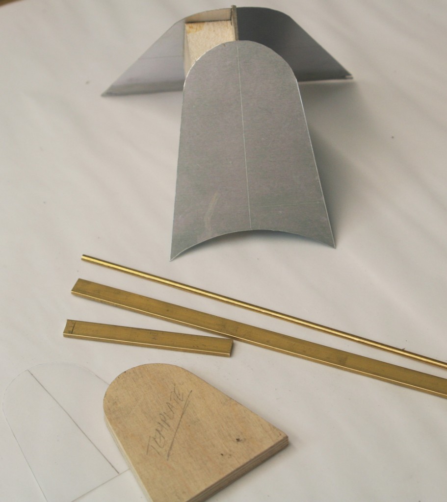
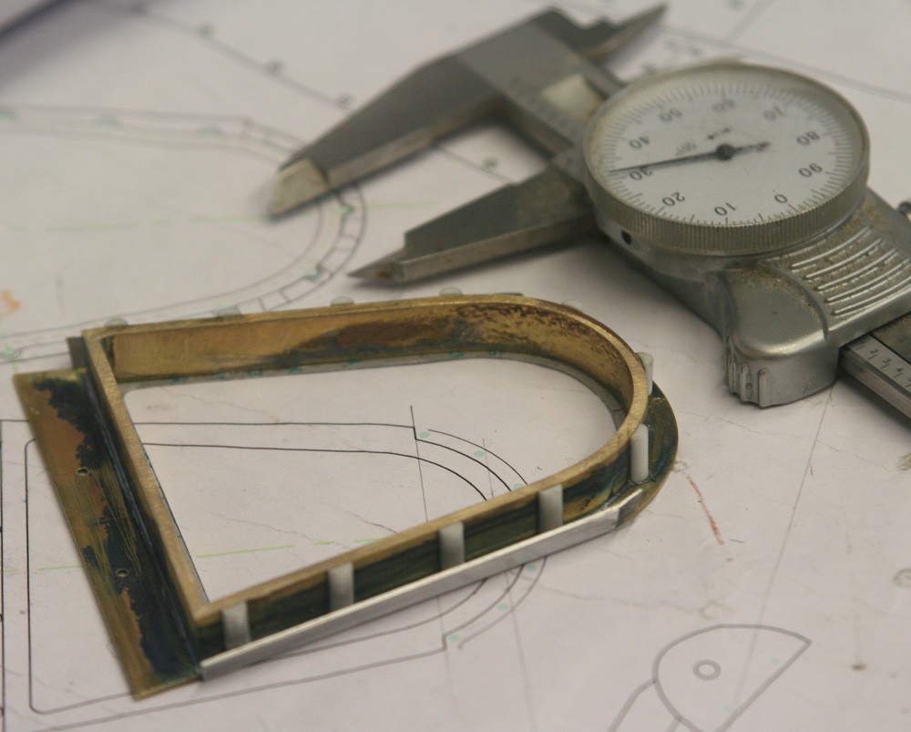
PHOTO 1: The crude model of the windscreen served no other purpose than to help me to focus my thoughts. The real work started with the arch-shaped frame that retains the armoured glass: First, a tracing of its internal shape, then a four-ply template around which to bend well annealed brass.
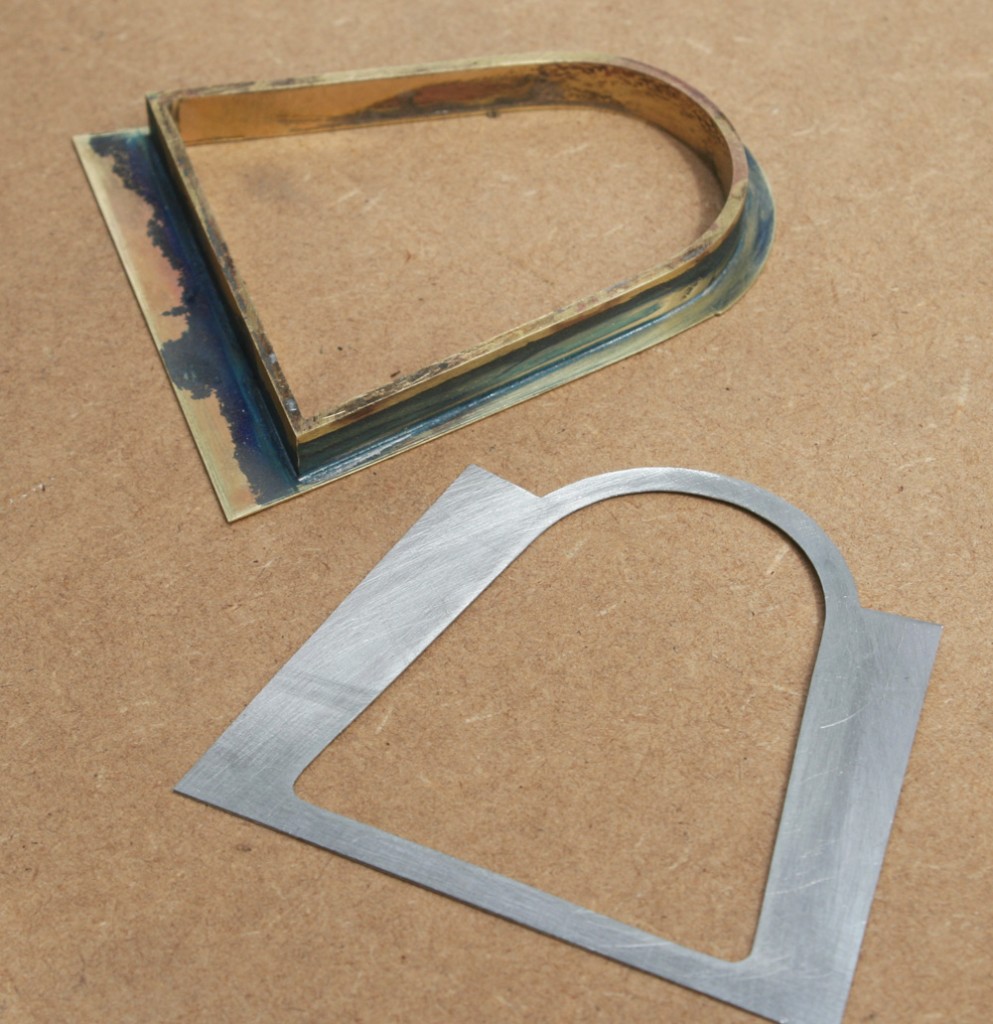
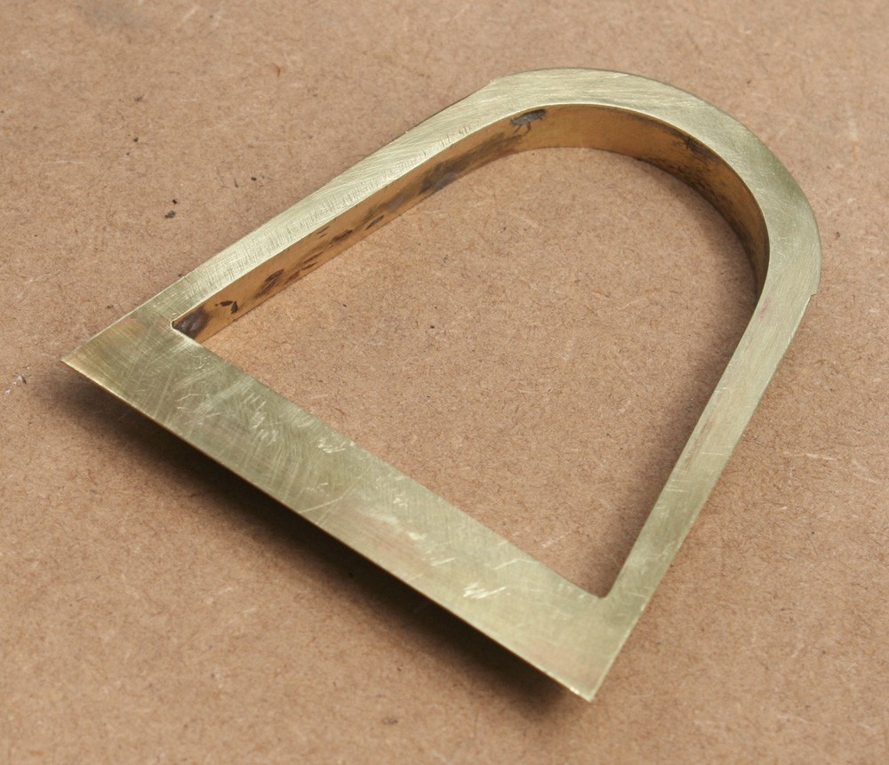
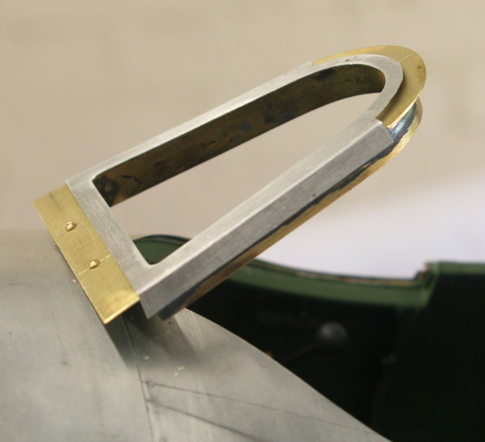
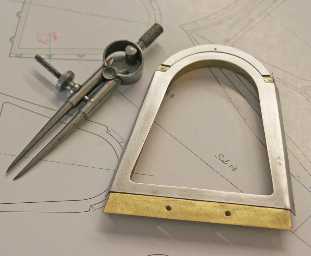
PHOTOS 2 and 3: With its downward limbs trimmed to length and squared up, the arch and its flat basal section are soldered together, and then soldered to a brass plate cut to the precise frontal profile of the windscreen. The aluminium outer skin (effectively a kind of ‘veneer’) is cut from lithoplate, such that when bent to the correct angle over the front of the brass frame the wing-like extensions form the sides of the finished frame. Thus the basic structure of the windscreen front panel emerges with the armoured glass residing on the inside.
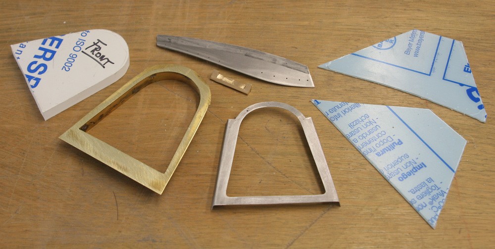
PHOTO 4: The ‘glass’ itself is cut to fit from 8mm Perspex. The two side panes are cut from crystal clear PETG sheet of around 1.5 mm thick or thereabouts, and these play a crucial role, both to help constrain the geometry of the entire assembly and to provide integral strength. Thus far I have ignored mention how the windshield assembly attaches to the fuselage (one of the biggest headaches at the planning stage), but this picture shows the key components: firstly, a small milled brass bracket – an ad hoc contrivance of my own – that acts as the lower fixing point for the front panel; secondly, one of the two graceful alloy angle plates that when screwed to the fuselage sides offer a firm anchorage for the lateral glazing and also for the extremities of the rearward of the two metal arches which in tandem make up the windshield assembly. This is more or less in line with the full-sized methodology. (More about the angle plates and the rear metal arch in the second of this two-part description.)
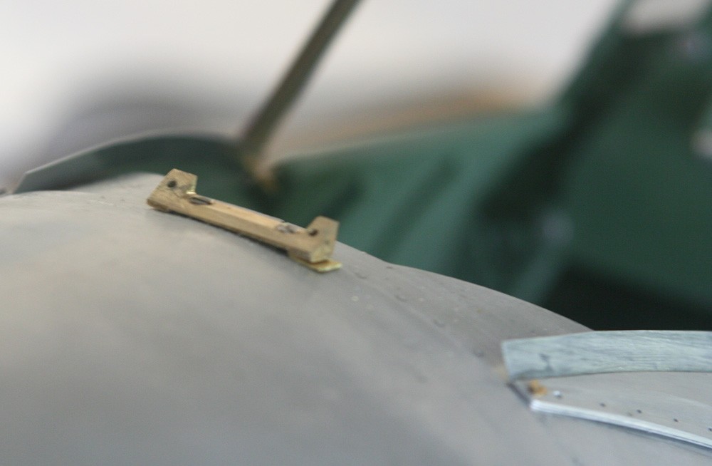
PHOTO 5: The brass bracket described above is now installed and held firmly in place at the top of the fuselage by two small wood screws driven into the underlying 1/4-in. ply doubler – a strongpoint in the wooden fuselage core. Its milled shape conforms to the raked angle of the windshield and two visible holes are tapped for 10BA retaining screws. The barely visible packing pieces serve to fine-tune the orientation of the windscreen forward panel to exact vertical.
PHOTO 6: Here the panel is seen slaved into position temporarily using two round head brass screws. During the assembly process it was removed and reinstalled many times.
PHOTO 7: Now the hitherto missing litho plate the caps the top of the arch has been added. In the full size aircraft this is formed integral with the two small lateral glazing bars, but in the model I made the latter separately for convenience and to simplify an otherwise challenging task. The screw holes for the sidebars are visible.
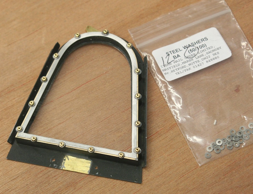
PHOTOS 8 and 9: In the full size aircraft the armoured ‘glass’ is retained in its alloy casting by a back-plate and 15 studs. In my model the shape of this casting is much simplified, although the omissions would be hard to detect. The two pictures show how I used half-round styrene strip to replicate the casting’s columnar sides. The gasket-like retaining plate is cut from litho plate (a rather delicate operation), and the prominent nuts and washers are real enough (12BA) but held in place with superglue. Note how the interior surfaces have received a coat of mat black paint.
