The windscreen - Part 2
Wednesday, 2nd November, 2016
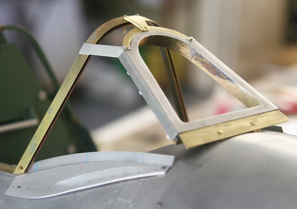
PHOTO 1: This informative picture shows all the key windscreen parts erected temporarily in position and how the overall shape is controlled by the front and rear arches, bridged at their apex by the base of the mirror post and upper lateral glazing bars. The assembly is secured to the fuselage by a small brass bracket hidden beneath the base of the front panel (described in Part-1) and by a pair of elegant angle plates screwed to the fuselage sides, The picture helps to elucidate the making of these plates. Note how the top margin is flat and canted upwards to receive the glazing, while its main body hugs the fuselage curvature. After some head scratching, I managed to create the piece by laminating 0.5 mm (or thereabouts) alloy sheet to 11-thou litho plate using superglue. The curvature is established in the thicker material first by trial and error, and then the flexible litho plate is glued on. Once the glue is dry, the upward set in the litho plate can be fairly easily established by using the flat of a steel rule to force the thinner metal back against the upper thicker curved edge. While I am pleased and relieved with this relatively simple solution to a potentially thorny problem, I see now that I have somewhat understated the thickness of these pieces, which is very evident in the full sized aircraft. 1.0 mm rather than 0.5 mm alloy might have been a better choice.
The rear windscreen arch merits a word or two: Because it performs the dual function of retaining the Perspex on one side and engaging by means of a much shallower recess the leading edge of the sliding canopy on the other, I needed to begin with an asymmetric H-section, where the bar of the H corresponds to the thickness of my glazing. The only way to achieve this was to make my own H-section from three 12-inch lengths of commercially sourced brass strip (two at 0.5 mm x 6.5 mm and at 2.5 mm x 1.5 mm). Sourcing the stock via the Internet was the easy part; but it took considerable care and patience to accurately fabricate the three parts together using solder paint and some gentle heat. Creating the arch shape over a ply former was relatively easy; and even though the solder did fracture in places during the bending this was repaired by the local application of a little more heat. The structure at the rear of the arch can be seen clearly in photo 9.
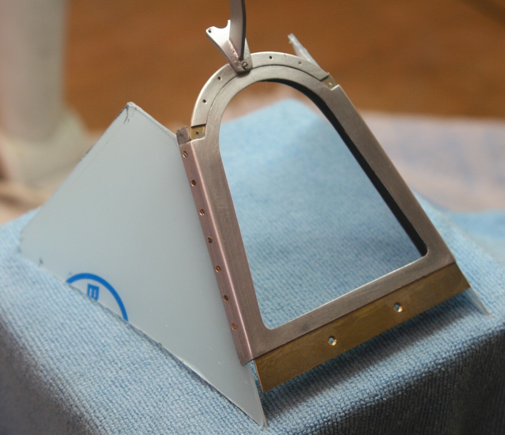
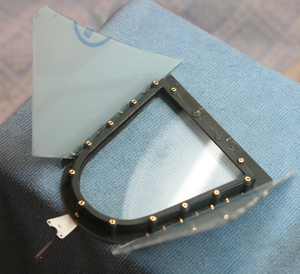
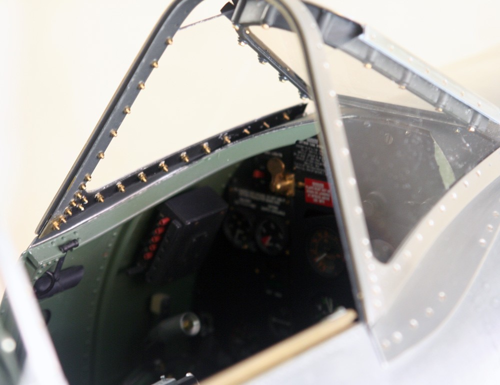
PHOTOS 2 and 3: In the Mk IX windscreen the lateral glazing panels are perfectly flat. Here they are being test fitted after having been cut to a template. Note that the mirror post had been completed by this stage. It consists of two pieces of brass, one gently curved and one flat, soft soldered together and sprayed with Alclad aluminium.
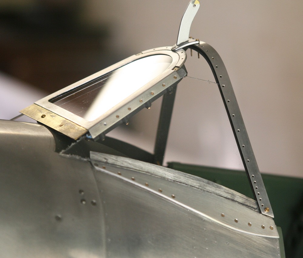
PHOTO 4: By this stage the two angle plates have been fixed permanently to the fuselage by a pattern of countersunk screws. The screws are easily self-tapped into the yielding composite of the underlying fuselage sides, but it needs care and judgement to prevent them from breaking though to the finished cockpit interior. The rear arch has been skinned with litho plate and drilled through for 14 BA countersunk screws. With the glazing and all the many screws tightened up the structure becomes very strong and rigid.
PHOTO 5: The lower edge of the glazing, where it meets the angle plate, is reinforced with internal and external glazing strips, both made from litho plate, and yet more screws. The brass screws shown here are slightly too long and will be replaces later. Struggling to capture the tiny nuts in inaccessible corners was not good for my blood pressure!
PHOTO 6: The structure is now nearing completion with the addition of the upper curved glazing panel and the internal and external parts of the two small glazing bars. I used 1.0 mm PETG for this tricky finale, relying on the pinching action of the structure itself to pull the clear plastic into the required curvature. It worked, just, but not without some tiny stress fractures appearing. I hope this corner cutting will not prove a mistake!
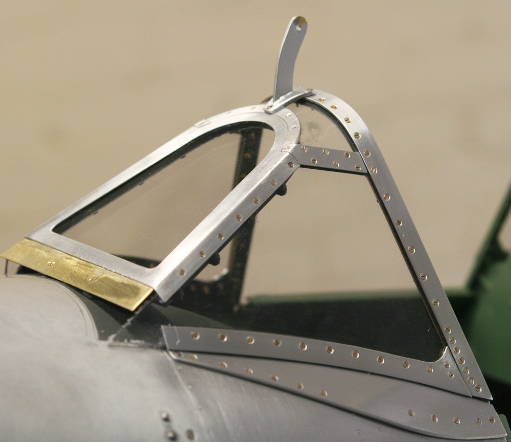
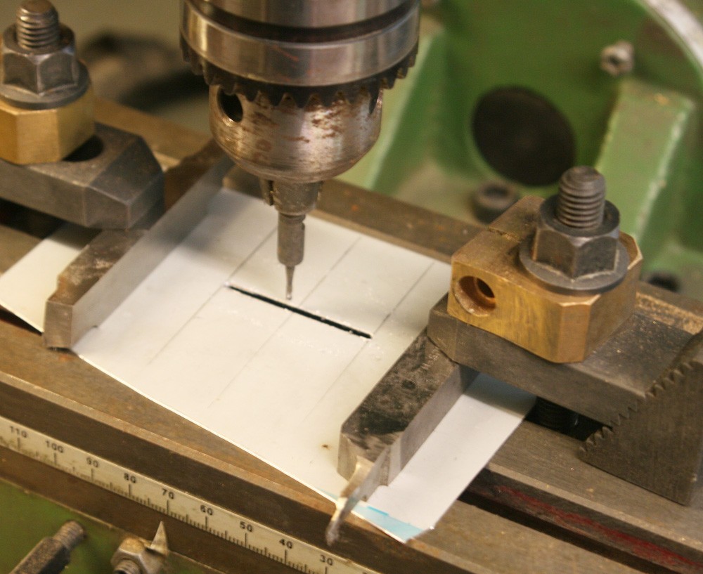
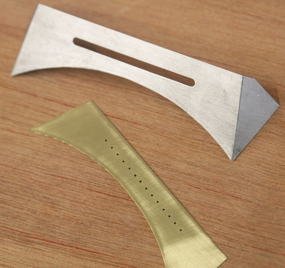
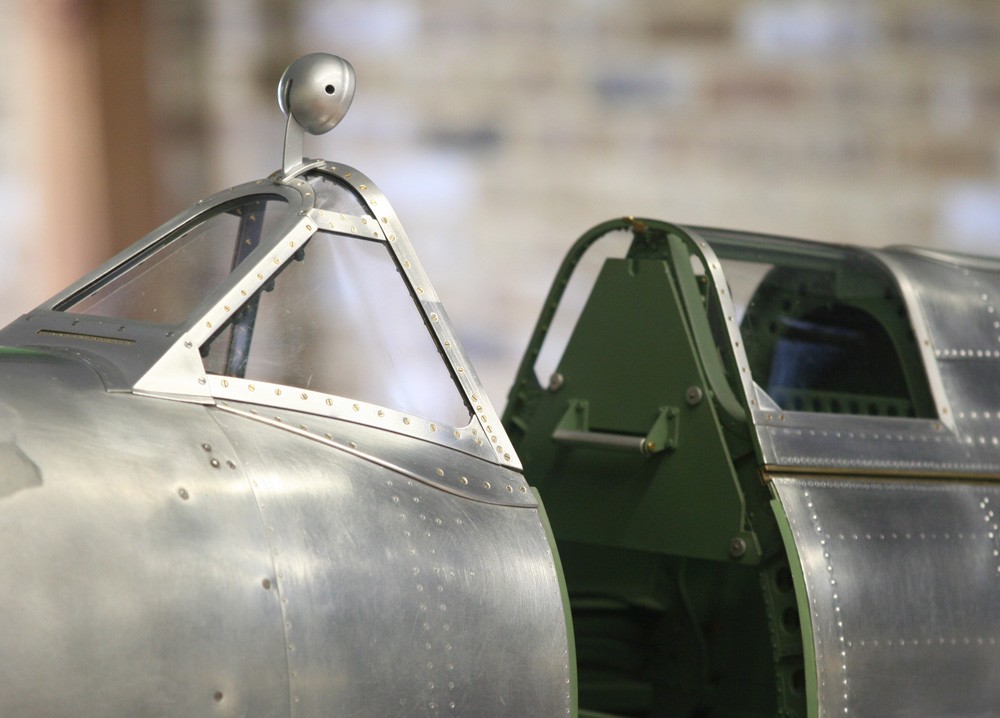
PHOTOS 7 and 8: All that remains is the tent-like fairing covering in the top of the fuel tank, and this incorporates the windscreen de-icing array. I simplified the de-icer pipe by drilling the serried row of holes in flat brass rather than over a curved surface, and the compromise hardly shows at all. An accurate slot in the fairing was easy to make with the help of a small-diameter milling cutter. Then, once everything had been carefully checked, the brass plate and fairing were installed permanently together with the small triangular filler pieces that serve to tidy up the flanks of the forward panel (photo 10).
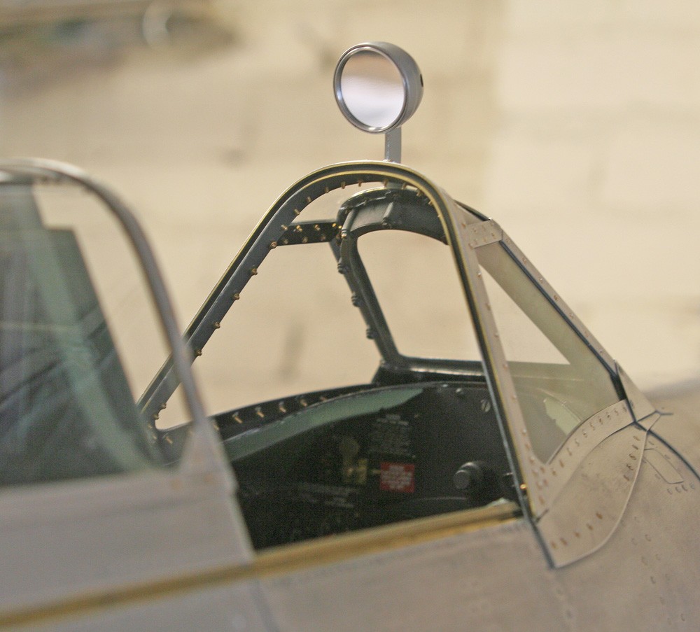
The mirror (PHOTOS 9 and 10)
I chose to make and fit the round late-type mirror. Its hemispherical body was lathe turned from a stub of scrap two-part epoxy casting resin, and the distinctive flat in the upper side filed by hand and eye prior to re-chucking the piece to part it off. I used a tiny dental bur to cut the neat little slot for the mirror post and the two access holes were carefully drilled by hand. The rim and its delicate internal retaining ring were turned from machine grade aluminium bar and the mirror itself cut from flawless mirror card that I obtained from a local dolls house supplier. Finally, before assembly, the whole lot was given a spray coat of Alclad aluminium to match the mirror post. The pictures testify to the close match between the real aluminium surface and the spray paint.