Time to fit the wings
Thursday, 3rd November, 2016
By the end of August 2016 I faced a landmark decision: After three years and six months of work, it was time to fit the wings to my Spitfire. From now on I would have ‘an aeroplane’ on my bench, but at a price: In place of three bulky but tolerably portable items, I would now have to cope with a single vast and unwieldy monster that would take two to handle. Moreover, there would be no removing the wings should unforeseen circumstances demand it. But however I might procrastinate, I knew that I had reached the stage where further significant progress was dependent on the big event.
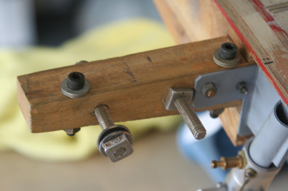
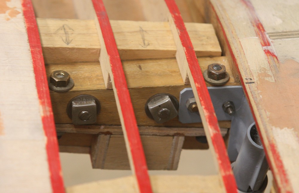
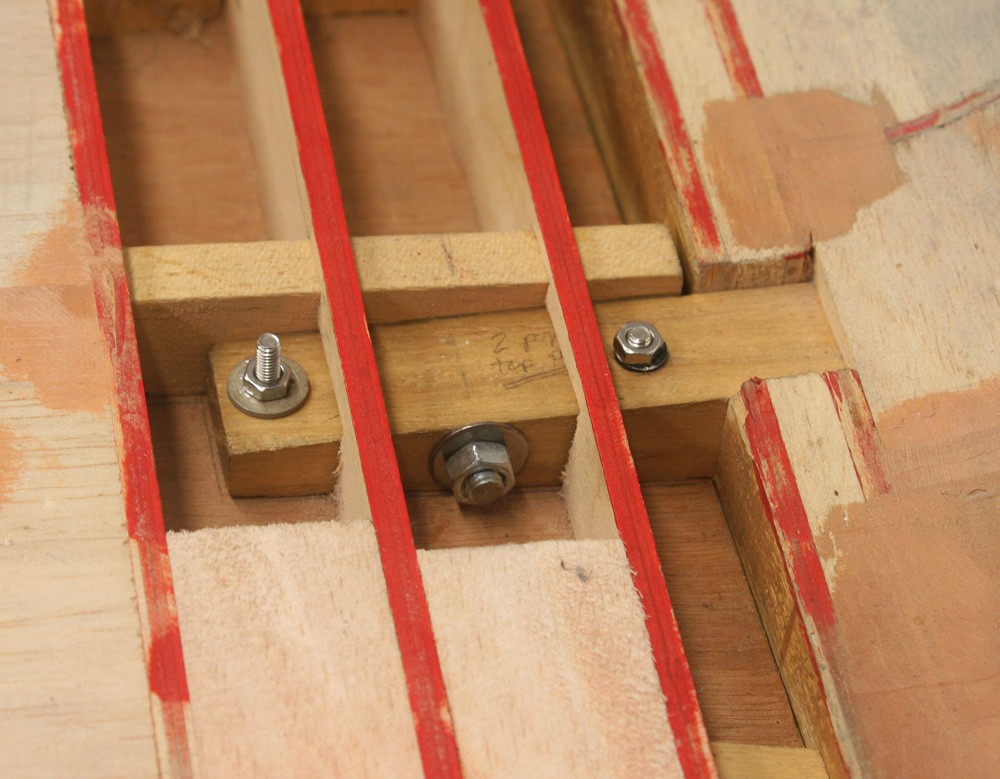
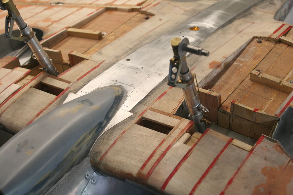
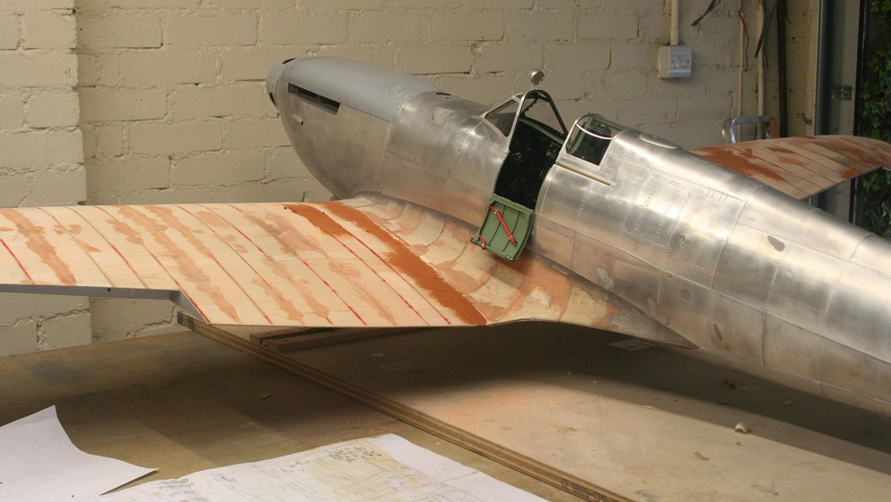
Those who have followed this blog will know that the wings of my model bear on heavy ash stub spars that project from the fuselage sides at the point of the dihedral break. There are seven bolts per side alternately in the horizontal and vertical plane (yes, I always over-engineer). The former pick up the hardwood wing spars and the latter the heavy plywood web over which the wing is built, thereby guaranteeing belt and braces in establishing and maintaining the dihedral. Strength and rigidity is further supplemented with the subsequent balsa wood infill used to plug the remaining gaps around the wing root area and eventually by the full external litho plate cladding.
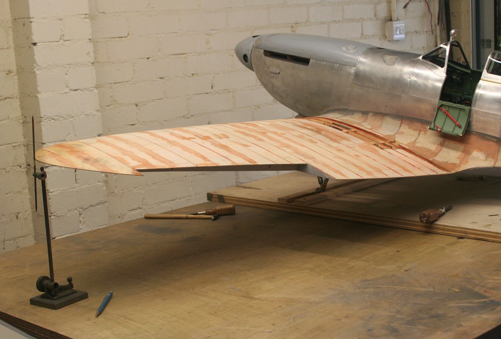
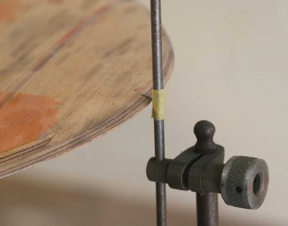
It is the addition of the glued balsa infill above and below the wing root that makes the wing assembly operation irrevocable, so it was crucial to check the dihedral angle one last time. To do this I simply set the model up on its building table and measured and compared the height between its surface and a datum point on both wing tips. Of course, this is conditional on the table being truly flat and on the undercarriage dimensions and geometry being conformable port and starboard. But that taken as given, my two measurements agreed to within two to three mm over a wingspan of more than two metres. I was content with that. A further critical requirement is that the mainplane trailing edges align precisely with the trailing edges of the wing root fillets as embodied in the fuselage structure. They did, and to within less than 0.5 mm.
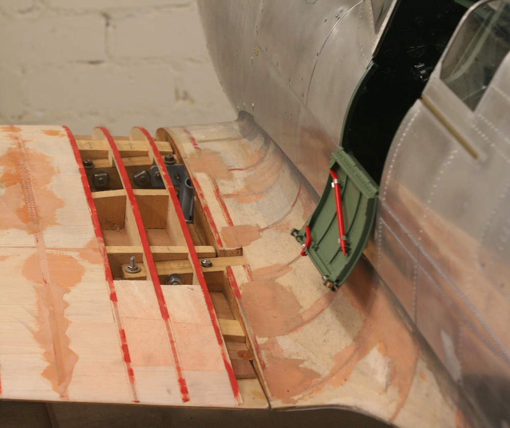
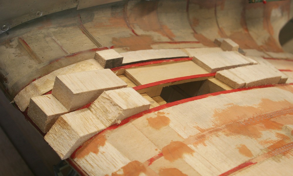
So with the wings bolted firmly and finally in position, the process of making good with scrap balsa the various residual gaps in the woodwork came as light relief, albeit that those areas immediately above the oleo leg arches required special treatment in the form of a approximately 1/8-in. thick balsa and three-ply laminate to roof them over. This was done in two stages: first the emplacement of the thin ply, and then the balsa.
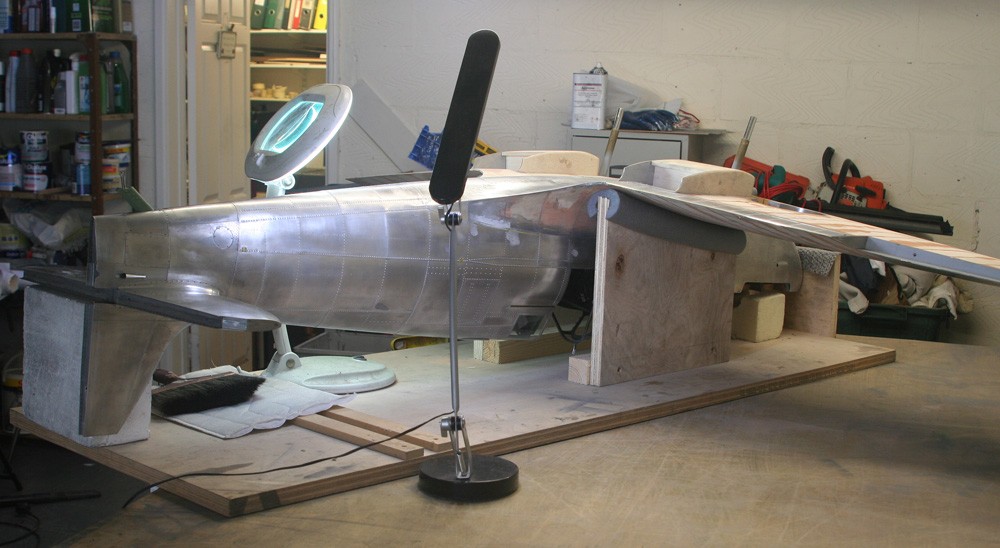
However, since this process involves both the underside and topside of the wing root area, I could no longer put off finding some method of supporting the inverted airframe. I had thought about this for some time: how to devise a safe and stable cradle that will serve over the many months and years that it will take to complete the underside of the model. My solution was simple enough. I took the top wing profile at the root directly from the drawings, inverted it and transferred it to two 15-in. by 13-in. slabs of sturdy one-inch ply and fixed them in the upright position on my building board with some one inch by one inch baton. Sheathed along their top concave edges with some 2-in. diameter domestic water pipe insulator, they serve as an excellent padded cradle to support the model without risk of damage to the soft balsa or litho plate skin. Any fore-aft movement is dampened by a third ply support that is bolted immediately forward of the aircraft’s nose, and through which the prop shaft passes and locks. With the further deployment of some styrene foam blocks to support the wing tips, I have a simple but stable cradle over which to focus my labours for the foreseeable future.