Blisters and cam-lock fasteners
Saturday, 28th January, 2017
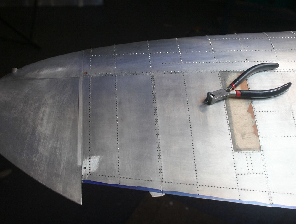
The onset of winter has temporarily curtailed operations on the airframe, since the model is now too big for my heated workshop and I do not relish the near freezing temperatures of an unheated garage. By mid-November I had completed the flaps – as described in my last entry – and I had also made good progress on the top wing panels. I won’t dwell on the basic alloy skinning process, which I have described so many times, both on this website and elsewhere. Suffice it to say that over most of the upper and lower wing surfaces, with the exception of the leading edges and tips, skinning can proceed at a rapid pace, thanks to the simple rectilinear shape of most of the panels and to gentle, unidirectional curvatures over the wing camber that render annealing both unnecessary and undesirable.
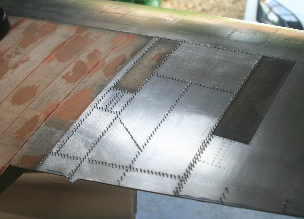
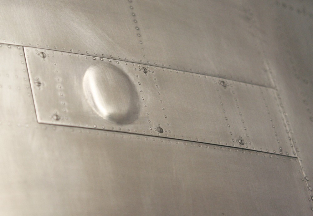
But not all is plain sailing: The several armament access panels on the upper and lower wing surfaces present a challenge because of their prominent clearance blisters and, to a lesser extent, their serried cam-lock fasteners. It is on both these features that I focus here.
The blisters
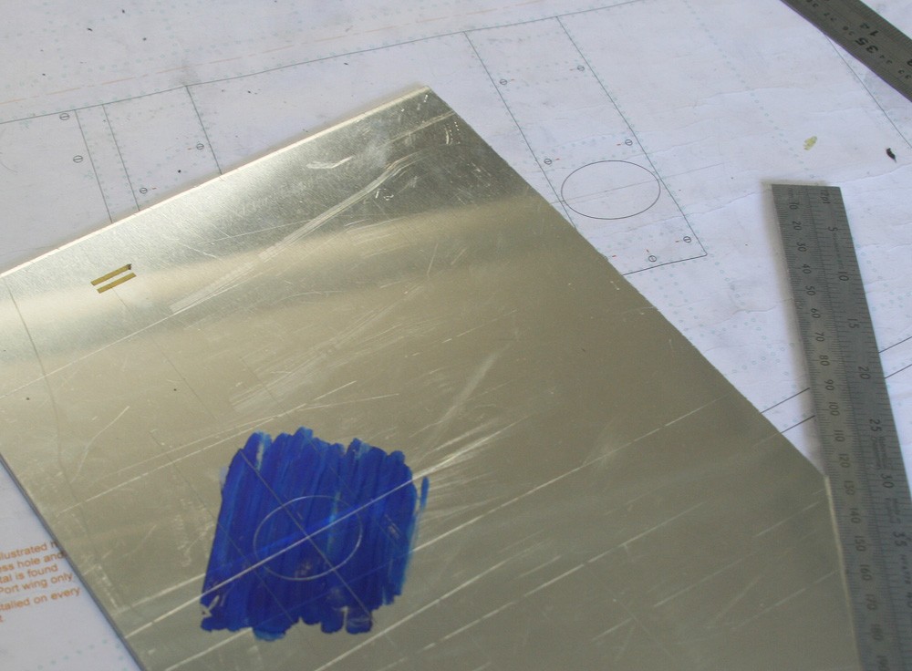
While the wing skin overall is 11-12 thou printers’ plate, I chose to make the access panels from slightly thicker 0.5 mm alloy to impart a subtle raised-up effect. Those enclosing the canon are particularly prominent, and even as I write I am undecided how best to tackle them. By contrast, the machine gun blisters are more modest, both in size and relief, so this is where I started.
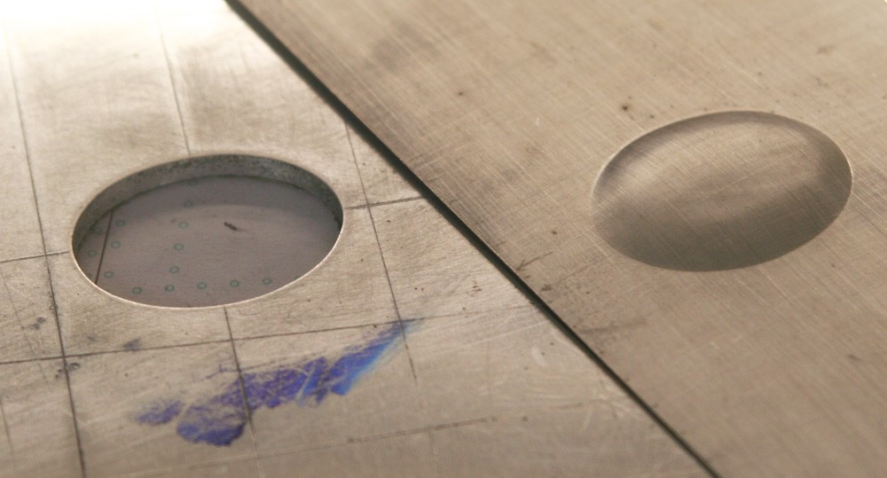
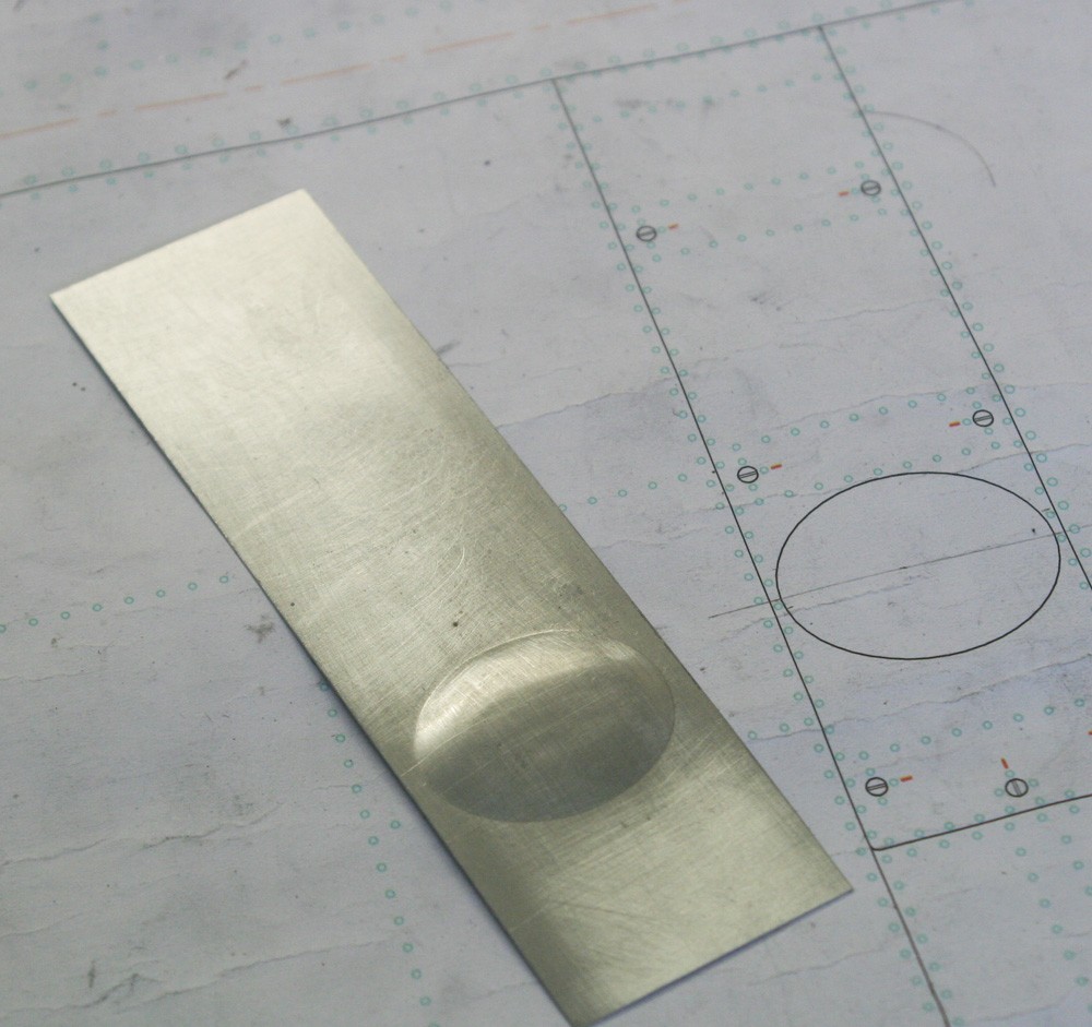
I chose the simplest possible former – a sheet of 1/8-in. aluminium pate with an oval hole cut in it to match precisely the circumference of the blister. With the work-piece cut oversize, annealed and clamped securely to the former, it is possible to force the softened metal down into the hole using a round-ended hardwood tool of about one-inch diameter. The action is a bit like using a mortar and pestle to grind spices, and once a sharp edge has been established around the periphery of the work it is possible to remove and relocate the work-piece accurately to check on progress. A simple card template is helpful here. The job is easier than it might seem, as evidenced by my getting two good blisters from three attempts.
Once the blister has been formed, the panel can be marked out and cut to size around it, and the position of all fasteners located and drilled with a 1/32-in pilot hole.
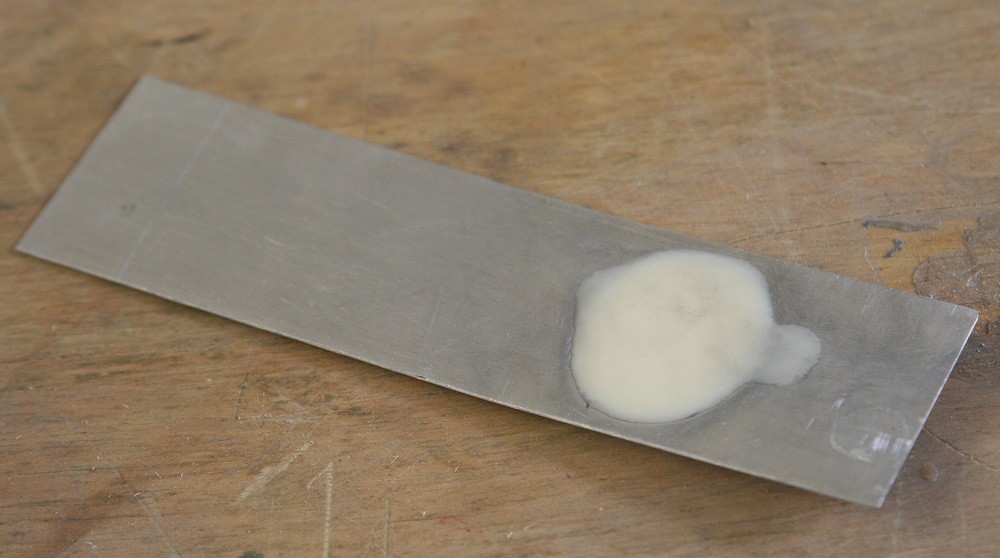
However, before it can be glued in place onto the wing, it is crucial to back fill the cavity formed by the blister, or the softened aluminium will inevitable become horribly dented with little prospect of repair. In this case I simply mixed some quick setting two-part casting resin and poured it into the cavity, sanding off any excess after the mix had hardened. Alternatively, I could have used two-part car body filler applied as a putty. When making panels with large blisters it would be essential to set the wing camber before the back filling, or the panel would become too rigid and inflexible to assume the required curvature, but with these small blisters it makes little difference.
Cam-lock fasteners
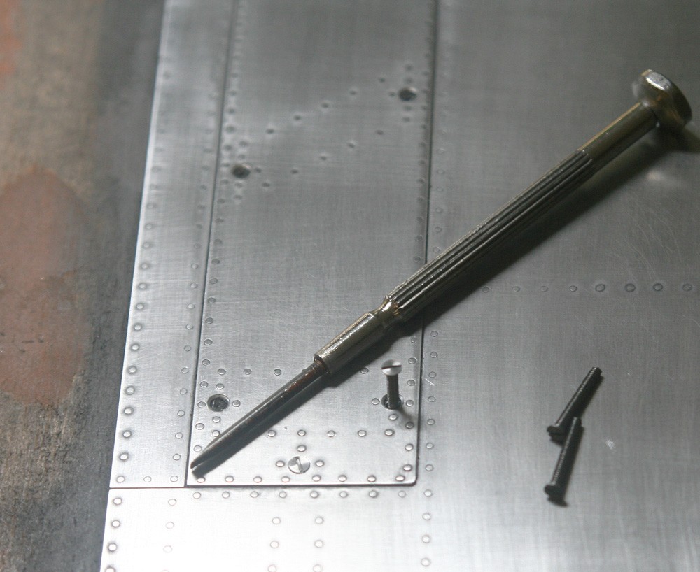
From the references I have studied of full sized Spitfires, the slotted cam-lock fasteners that secure the armament access panels are either flat or have a very shallow dome shape. I chose the former, simply because they can be very easily and effectively represented using model engineers’ countersunk steel screws, in this case 10 BA.
The pitfall here is in the ‘countersinking’: Such a simple operation yet fraught with difficulty when applied to very thin and soft aluminium plate. The reason is that it is ridiculously easy not only to end up with slight but obvious variations in the diameter, shape and depth of the cup-shaped hole, but also to have the tool dig in and tear or otherwise distort the work horribly, with the result that the not only is the entire work-piece ruined but it is very easy to cause further damage in trying to remove it. And from this it will be obvious that it is only possible to form the countersinks at all once the plate has been glued tight to the wooden substrate.
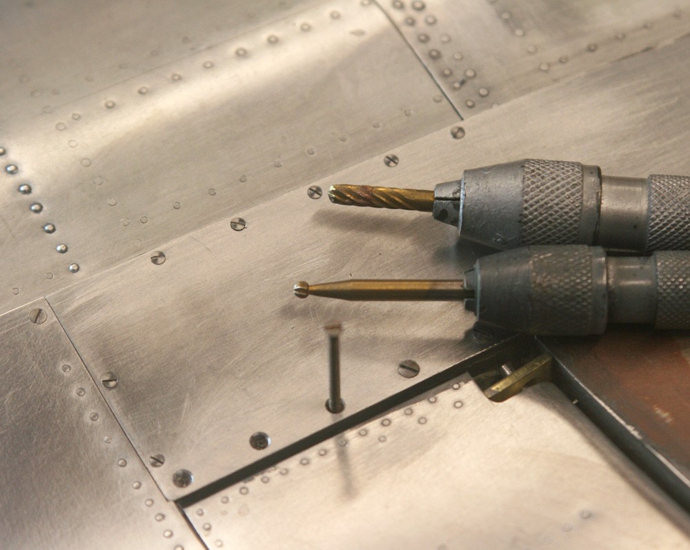
After many years’ experience I have not yet come up with a foolproof method, and would love to be advised. But I have arrived at a procedure that is relatively safe and that for the most part works. Before starting it is necessary to open up the original pilot hole just sufficiently for the steel screw to self-tap through the metal and into the underlying wood, be it balsa or ply. It is vital here that the drill bit is square tangentially to the surface, or irregularities will show in the angle at which the screw heads bed down. With that done it is also vital thereafter to proceed slowly and by stages. I select a series of twist drills by which to progressively develop the countersink. This way the metal/glue/balsa combination into which I’m cutting has less chance to tear or distort. For the finishing touches I switch from twist drills to ball ended burrs. I’ve found that these greatly facilitate my ability to get not only a crisp, clean and perfectly circular finish to the small cavity but also – and more importantly – to ensure that each is identical to its neighbour. This cannot be overstressed, because when making a line of close-spaced countersunk holes, even the smallest irregularity screams out once the screws are emplaced. Put another way, the job looses all pretence of having been ‘engineered’.
It will be obvious to all that the method I describe is tedious in the extreme and it requires a great deal of patience, care and judgement. It is very helpful to have a series of pin chucks of different sizes available so that time is not wasted constantly changing the tool bits. And it is also prudent to do all the holes in an adjacent set together, since this helps in achieving that all-important consistency.
This really is an example of where the devil is in the detail – detail that in a few seconds of lost concentration can irrevocably mar many hours of beautifully executed work.