Radiator fairings resumed
Friday, 27th October, 2017
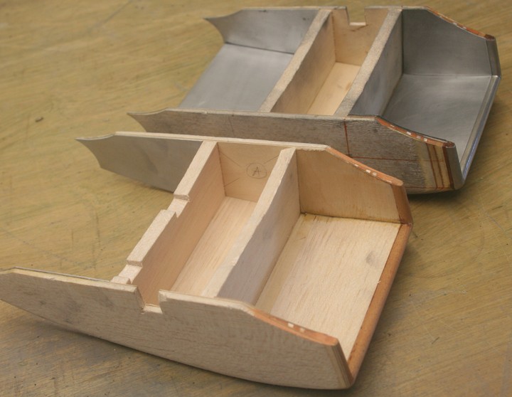
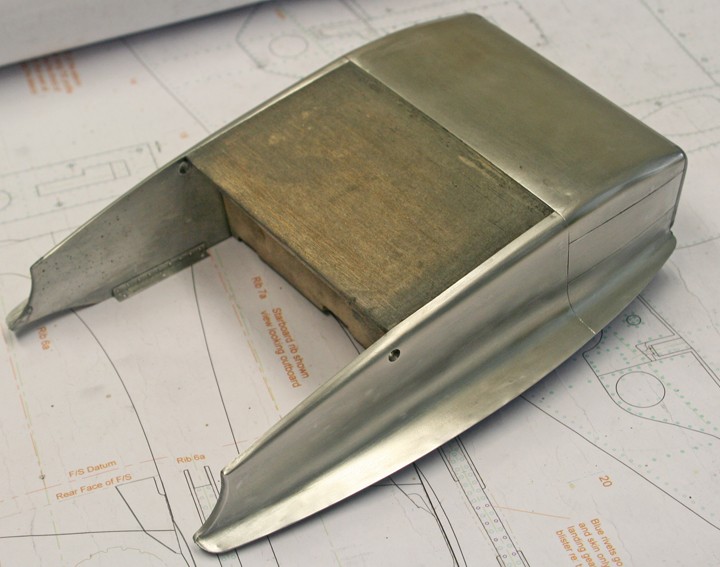
With most of the wing undersurfaces finished, I turned during the late summer just gone to the box-like radiator fairing shells built and set aside three years previously (see my blog of June 22, 2014). However, on dusting these down I discovered that I had made their gently curving flanks too flat, with the result that the rectangular air intakes were 3/16-in too wide – an unacceptable and exasperating error that cost valuable time spent on ‘padding out’ the converging interior shell walls, while sanding an equivalent amount of material away from the exterior. How I made such a basic gaffe baffles me.
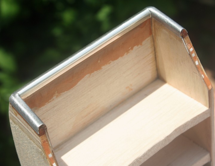
In establishing a sequence for the metal work, it was clear that the narrow U-shaped ‘lip’ around the intake would have to be applied first, and that I would need to compromise by making it in three parts rather than one, while also substituting malleable pewter sheet for litho plate. That way I could mould the soft metal strips snugly around the hardwood leading edge with its two tight 90-degree corners, splicing the metal in with a sharp scalpel blade where the pieces abutted. While visible, the joins are neat, discrete and not at all incongruous. I used superglue to attach the pewter, removing unsightly overspills with an acetone dampened cloth. With the leading edge in place the remaining interior surfaces of the fairings up to the radiator block came next, and they were straightforward to line out with un-annealed litho plate and contact adhesive.
Two noticeable features of the fairing assembly are the big hinge bolts that retain the door (or flap). These are recessed deep into the flanks and they require two fairly large holes, one per side. Drilling accurately into a combination of soft balsa and relatively hard plywood is not easy, so I opened the holes by stages, checking as I went. The slightest misalignment here would mean that the door would not sit square, or even fit at all! Once satisfied, I lined the holes with thin-walled alloy tube. I will deal with the fairing doors in a subsequent blog.
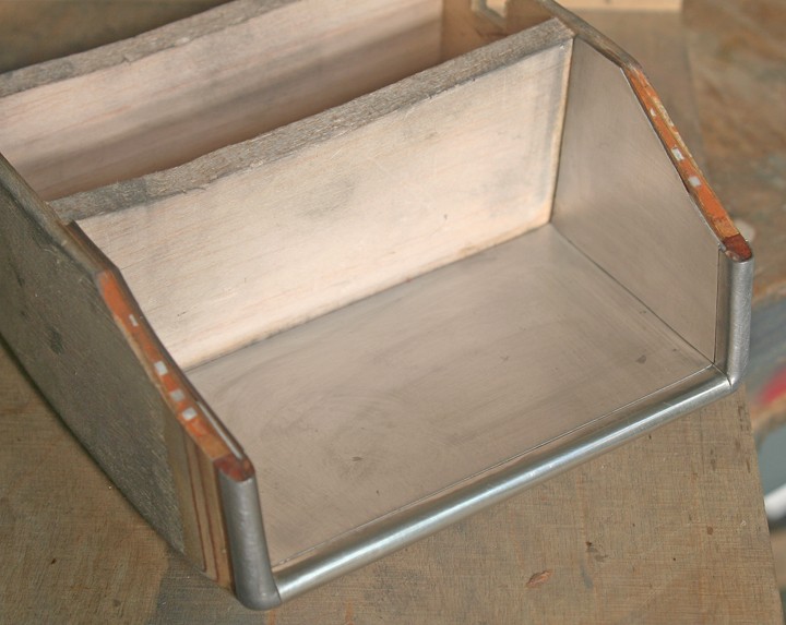
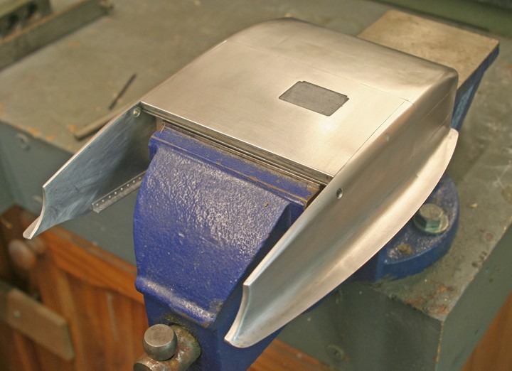
As my photos show, I began the metal skinning process at the front end of the assembly: First came the two small rectangular panels located midway down the flanks, then the much larger crosswise plate that bridges them together. The corners here are tight with some fore-aft compound curvature, but with careful annealing the metal can be ‘massaged’ into shape fairly easily.
Now for the bell-shaped flanges that are so much a feature of the Spitfire’s radiator fairings. To cater for these I needed to bolt the partly covered wooden shell in its exact position on the wing, using a set of small internal brackets made for the purpose. My photo shows one of them riveted to the inside of the fairing and drilled for four 12BA cheesehead screws. These screws self-tap through the alloy wing skin and into the underlying wood, allowing the assembly to be installed and removed again at will.
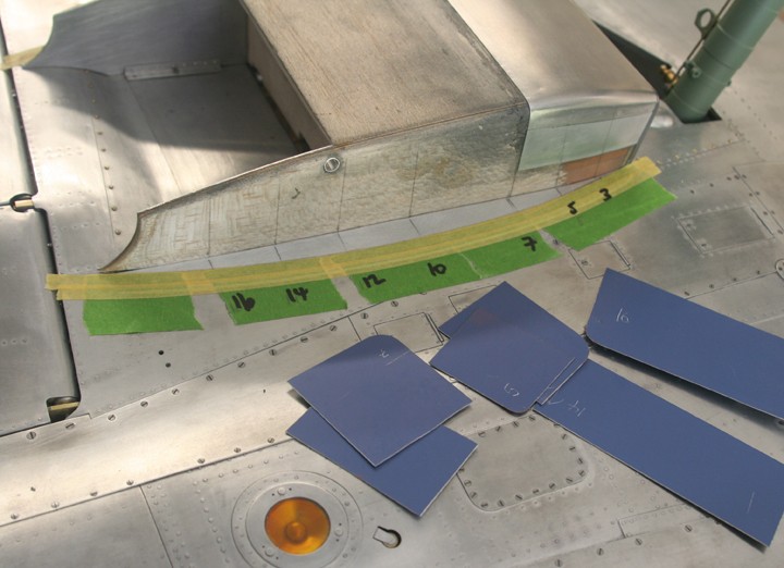
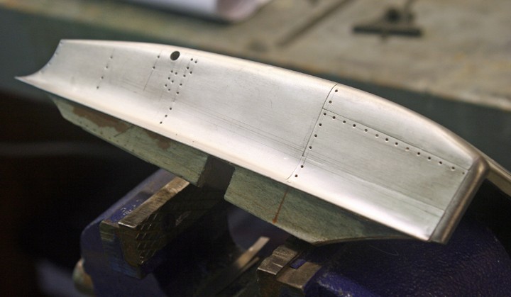
The next stage involved transferring the plan-view outline of the flanges from the drawing to 0.5 mm aluminium sheet. The photo shows the port side plate taped into position abutting the fairing flank and snugged downed onto the wing. Note the inscribed station positions and the corresponding templates that I made to constrain the flared shape of the flange.
Capturing the bell-shape is pretty straightforward, and it involves easy-sand wood filler. I liken it to ‘sculpting’ in reverse, where the shape is built up progressively from the inside outwards by applying successive layers of filler with the finger tips. Each stage is allowed to dry before the next is put on – a process that can be accelerated with the help of a low-heat hairdryer. It takes patience, frequent use of the templates and careful sanding to achieve the finished concave shape without cutting into the soft balsa sides of the workpiece. Much the same process was used when making the fillets at the root of the horizontal stabiliser.
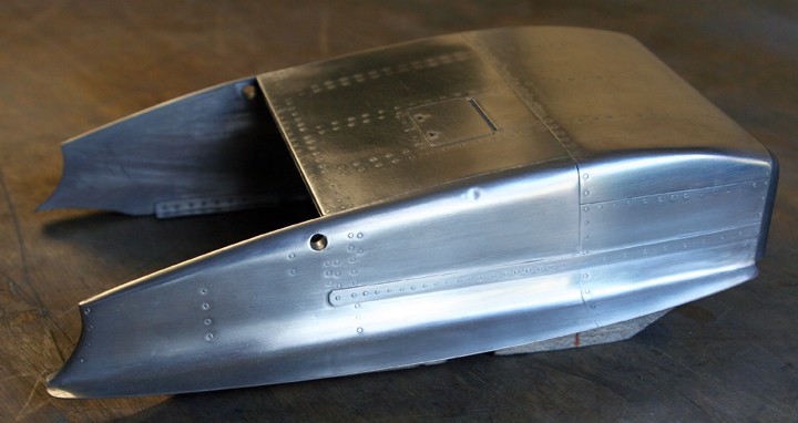
With both the port and starboard flanges grafted in place, the way is clear to install the final piece of top skin. The problem, however, is that this entire section – comprising of the aftermost two thirds of the fairing assembly – should be installed as one piece. I was under no illusions about this; it might not only tax my panel beating skills to beyond their limit, but also risk a disastrous misalignment at the glueing stage. On the basis that a further compromise was better than an irretrievably botched job, I decided to install this part in three pieces instead of one, thereby accepting two false panel lines running fore-aft in line with the outer edges of the door.
The rectilinear belly section (pierced for a small inspection cover) was simplicity itself; the two side pieces not so. Yet with repeated annealing of the metal and a slow, methodical approach to developing the relatively complex shape, I achieved a result that I could live with. I deliberately left the side pieces a mm or so oversize all round (apart from along the ‘faux’ seam lines), filing away the slight overhang only after the part had been glued firmly into position with EvoStik, and consolidated all around by a carefully applied run of thin superglue.
It took about two days to metal skin each fairing, and the result is a strong and rigid structure. After the ubiquitous rivet detail (which took a further day or so), only the narrow reinforcing strips that feature along the flanks and around their flanges remained. I cut these from aluminium sheet and glued them in place with medium viscosity cyanoacrylate. So long as the mating surfaces are clean and degreased, the glue forms a reliable enough metal-to-metal bond, which can then be reinforced by subsequent drilling and filling with rivets (and screws in the case of the curved flange stiffeners).
If this has been a longer than usual diary entry, the reason might be that the metal skinning of the Spitfire’s twin radiator fairings presents more than the usual quota of challenges!