Canopy framework
Friday, 19th October, 2012
The canopy frame is not a straightforward piece. It took careful study of the NAA drawings before I was able to understand the complexities of its interior structure, so as to resolve a basic shape over which to develop the detail in sheet metal.
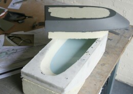
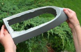
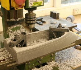
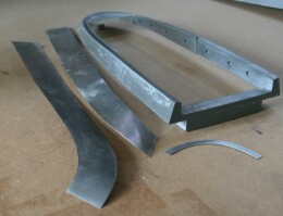
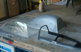
It was crucial to capture the external contours of the frame faithfully so it would fit snugly into the glazing. This caused much head scratching, yet in hindsight the answer was obvious: to take a second resin casting from the original silicone rubber mould that I had used to produce the vac-forming tool. I modified the mould by filling it with more silicone rubber to a line corresponding to the top of the frame, adding, when the rubber was set, an internal core rough-cut from modelling foam. My pictures show the resulting epoxy resin blank. The first task was to sand the true underside of the frame perfectly flat. Then I was able to clamp it to my milling machine and cut the upper surfaces accurately, including the break of slope that occurs about half way down. Allowing for the inward sloping sides – the angle of which increases going aft – I marked the plan view and removed most excess material with a power jig-saw, then shaped the sloping sides using Permagrit hand tools.
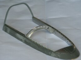
Beginning the detail work, I fashioned the small turtle deck at the rear of the frame with its supporting beam and two small brackets, filling the cavity so created with plastic metal, both to strengthen the job and to support subsequent rivet detail. I skinned the inner sides of the frame with 0.5 mm aluminium alloy sheet fixed with a combination of contact adhesive and Superglue, including some structural detail at the fore end of the frame where it bolts to the sliding trucks port and starboard.
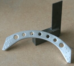
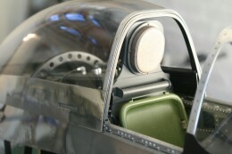
A prominent feature inside the canopy is the arched beam about half way down. This is a sheet-aluminium pressing with flanged edges and lightening holes, and with care it is not difficult to do. I made a pattern from aluminium alloy plate as thick as the flanges are deep, allowing 0.5 mm all round – the gauge of the sheet metal I proposed to use. Using the pattern as a stencil I transferred the holes onto the work piece and drilled out the centres, leaving excess material around the circumferences from which to create shallow flanges. With the work-piece clamped to the pattern, I used a small tapered drift and a light hammer to drive the alloy down into all seven of the lightening holes, truing-up the newly created flange edges with a flat file afterwards. Finally, I relocated the work-piece over the pattern and created the deeper exterior flanges using a small hardwood mallet made specifically for this kind of job, finishing by filing them true against the plane of the pattern and dressing out blemishes with abrasive paper.
Most of the remaining detail will be apparent from my photographs, but one important item is worthy of mention: The arch support the front of the canopy – a folded metal section in the real aircraft – is an epoxy resin casting in my model. I simply upended and suspended the original foam-board and ply pattern into a small biscuit tin, pouring silicone rubber to just over the dimension indicated on the drawing. This shallow mould produced a flat, plate-like epoxy resin casting, from which I carefully cut away the interior, leaving an arch that matched precisely the canopy’s frontal cross section and its downward slope to the windshield. This piece was rather brittle during the clean-up process, but when fitted and drilled and tapped for the external glazing strip, the entire assembly became robust.
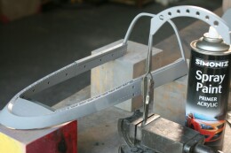
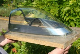
With the interior dome head riveting completed and the structure primed and painted black, the frame was now ready for assembly into its ‘Pesrpex’. Here I used distinctly ‘non-scale’ countersunk screws self-tapped through the PETG and into the resin. These would be completely invisible beneath the external aluminium skins, which I had already cut and shaped from litho-plate, using a spare (dispensable) canopy supported over the heavy vac-form tool as a former on which to work, thus avoiding damage to the real glazing. The exterior skin is fixed in place initially using Evostick contact adhesive. Since I had not yet cut away the excess basal PETG, I was able at this stage to nail the entire assembly to a sturdy timber base board and mount it vertically in my bench vice, giving a stable platform on which to carry out the exterior riveting and the final polishing in comfort.
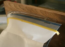
A prime requirement throughout the final stages was to prevent damage to the clear plastic. Drilling out rivet runs and, more especially, sanding down afterwards creates a lot of abrasive dust. Careless contact with tools or dirty fingers can become indelibly recorded on the pristine PETG surface. I protected the exterior using several layers of paper and high quality Tamiya masking tape, and I kept the interior as clean as possible with frequent applications of an air duster. Inevitably the job suffered minor scratches, but you have to look hard to see them.

Previous post

The vac-formed canopy
Next post

The Mustang's tyres

