A pause to look back
Monday, 25th April, 2011
I began this diary in 2009, four years after starting the model. So at this juncture, with the wings and fuselage finally united and the skinning complete, I thought it might be appropriate to look back to the beginning to show something of the underlying methodology I adopted in the construction. Essentially, beneath its skin my model is made of wood; what the eye sees is mostly metal. The trick is grafting the two together as the result of what I like to call 'sleight of hand'.
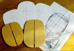
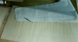
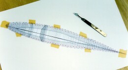
I have many thousands of North American Aviation manufacturing drawings of the P-51 through its various marks, along with the workshop manuals and handbooks. As I come to a component I am able to look it up in the Parts Catalogue, cross reference the drawing number, download a digitised copy from DVD, scale it on my computer and print it to size. Pure luxury! But aircraft manufacturers do not bother with 'three-views', so my first steps relied heavily on the excellent P-51D drawings by Arthur Bentley, which I had enlarged to 1:5 scale (Big pieces of paper!).
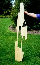
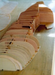
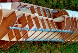
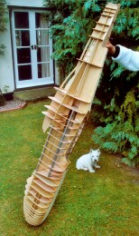
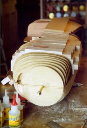
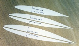
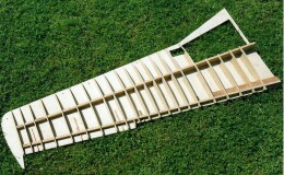
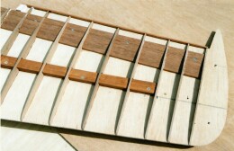
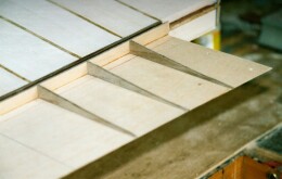
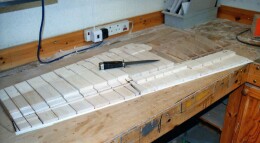
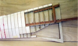
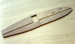
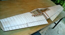
Arthur was able to let me have accurate wing, empenage and fuselage cross sections, which enabled me to begin cutting wood. Again, I hope the photographs speak for themselves: The entire wing is cut in plan view from two pieces of 5mm ply wood (the flaps and ailerons being separated at a later stage). The three dimensional shape is developed from a series of 4mm ply cross sections at the nominated stations, and the spaces between are filled with balsa wood. The structure includes robust mahogany front and rear spars to provide structural integrity and a firm foundation for the landing gear. The spars also define and sustain the dihedral, which is consolidated by steel plates at the centre section. Of course, features such as wheel bays, gun ports and control surfaces have to be factored in, but essentially the construction method is simple.
The same goes for the fuselage, although here the fundamental design problem was how to cater for the big cockpit space without compromising strength. My solution involved grafting four sturdy aluminium longerons (which feature in the real aeroplane) to the wooden structure, and then removing mostly everything in between. The longerons thereby create a rectangular box section and the outer skin provides additional strength and rigidity.
The emergent fuselage incorporates the embedded prop shaft, provision for the exhaust stack assembly, cockpit floor, radiator and oil cooler inlets and tail wheel bay, all of which called for a certain amount of forward thinking. Likewise, as mentioned above, in building the wing I had to make early contingency for the capacious main wheel bays, which would have significant structural implications given the quantity of material that would have to be removed. Of equal concern was to ensure that the control surfaces fitted and faired accurately, since these would have to be made as separate items 'regrafted' to the mainplanes using telescoping brass tubular fixings by way of the hinges in the real thing.
I made one significant omission: Despite the urgings of Arthur Bentley I refrained from attempting to incorporate the subtle 'washout' that is a feature of the P-51 wing. Washout is a technical term for the slight variation in the angle of attack between the wing root and tip; in other words, a very slight twist in the wing. Experts will recognise this, but most will not. My rationale is that it is better to omit what may be beyond my capabilities than to attempt and make a botch of it.
Last, but by no means least, a crucial consideration at this formative stage was to devise a means to attach what would become a heavy one-piece wing to the fuselage. The criteria included not just strength but also access to the fixings at a later stage when most of the cockpit components would have been installed. My answer was to used four big bolts held captive in the mahogany wing spars and, for additional security, a central and forward fixing formed from a steel plate bolted both to the apex of the wing leading edge and to the plywood axial web over which the fuselage is built. I made the under fuselage seating from two pieces of 1.25in. thick mahogany profiled to the upper wing shape and bolted to the underside of the lower longerons then drilled through to take the wing studs. All this, of course, depended on there being sufficient access within the built-up cockpit to locate and tighten the four paired down nuts when the time came, and to manoeuvre into a restricted space the large cockpit floor assemblies that serve to hide the fixings. As it turned out there was... but only just!
Previous post

Wing root fairings
Next post

Grappling with gremlins