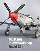
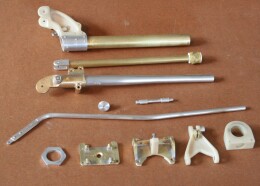
Control column assembly
Sunday, 15th January, 2012
Anyone who has followed this log may have noted that, while much of my work is done in metal, I am not afraid to make use of alternative materials if that makes a job easier, or even feasible. Over the years I have accumulated some skills as a ‘model engineer’, yet there remain many tasks that in metal take me out of my comfort zone, and this is where what I like to call a ‘hybrid’ approach comes in useful.
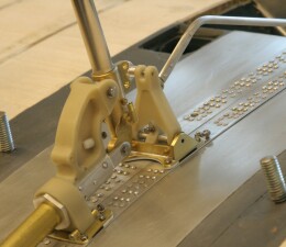
In the full-sized aircraft the control stick and aileron torque tube assembly includes several castings among its numerous components. Clearly, for just one model there is no need to make castings; they can be machined directly from solid aluminium or brass stock. But where no un-due stresses or loadings are involved, they can also be machined, and more easily, from material such as resin.
I habitually keep the residue from two-part resin casting jobs for just this purpose, and if I do not have sufficient leftovers I pour a blank specially. Resin turns beautifully in a small lathe and my mini-milling machine takes to it too. Perhaps the biggest advantage is that it is so quick and easy to cut and file accurately by hand (while wearing a mask!), and it gives a perfectly smooth finish in small components that would be impossible with even the finest grained hard wood. So when it came to the control column ‘castings’, this was my preferred route, and through a combination of machine milling and drilling and hand filing, I was able to produce good copies quickly and easily, using the NAA manufacturing drawings as my guide.
I raise this because I believe that for the sort of models I make, which are essentially static replicas, with few moving parts, the technique is ‘legitimate’. It may not be engineering in the pure sense of the term, but it enables in a static model a result that is accurate and stable and achieved for the minimum expenditure of time and energy.
That said, the majority of components for the column were very simple to produce, being little more that sections cut from standard stock brass or aluminium alloy tube. An exception is the control column itself, which due to its elegant taper, required turning from solid alloy bar. As to the rest, the parts were easily cut or turned in brass and soft soldered together, as the pictures here show.
Where nut, bolts and washers are used in the real thing, so I used the same, scaled down by one-fifth from the drawings. As the pictures show, the control stick assembly and its static aileron locking mechanism are bolted directly to the top wing. Gratifyingly, once installed the column worked just as intended, with a lovely silk smooth forward, backward and lateral action – a feature I was very grateful for much later when it came to installing minor cockpit furnishings: The ability to move the stick out of the way made the difference between being able get my hand in to fit many a small component in place or to tighten tiny and otherwise inaccessible nuts or screws.
If I have one concern about this technique it is the metal-resin bond. I use cyanoacrylate glues, which are highly effective. Just as in soldering, I take every precaution to keep the bonded joints scrupulously clean before applying glue; even so I have no way of predicting the long-term permanence of the bond or if it will degrade with time, so wherever possible I reinforce all chemical joins with some form of good old fashioned mechanical fixings – ‘belt and braces’, you might say!
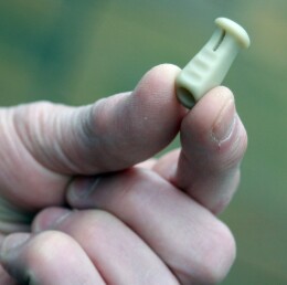
The very last component I made was the handgrip, complete with trigger and button, and again I chose resin for this. There is no great technique to achieving the shape, just patience, care and a good two-view drawing. I drilled and rough cut a resin blank, pushed it on to the top of the column and started carving, filing and sanding. When the work-piece looked like a handgrip from the front, side and above, I knew the job was done!


Previous post

Retrospective: Auxiliary fuel tank
Next post

The pilot's seat