Retrospective: Wheelbay structure
Wednesday, 1st January, 2014
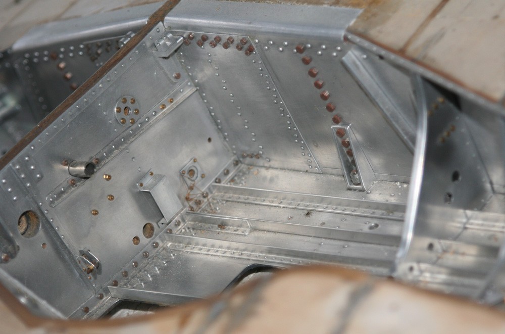
Developing the structural architecture within the Mustang’s capacious wheel bays was an enjoyable and rewarding process, despite the considerable repetition required to make and install the numerous components, particularly the close-spaced and close-riveted stringers to which the skin plates are attached. Not only did this stage breathe life into a key area of the model, it also provided further structural integrity to the central region of the wing forward of the main spar where it was most needed.
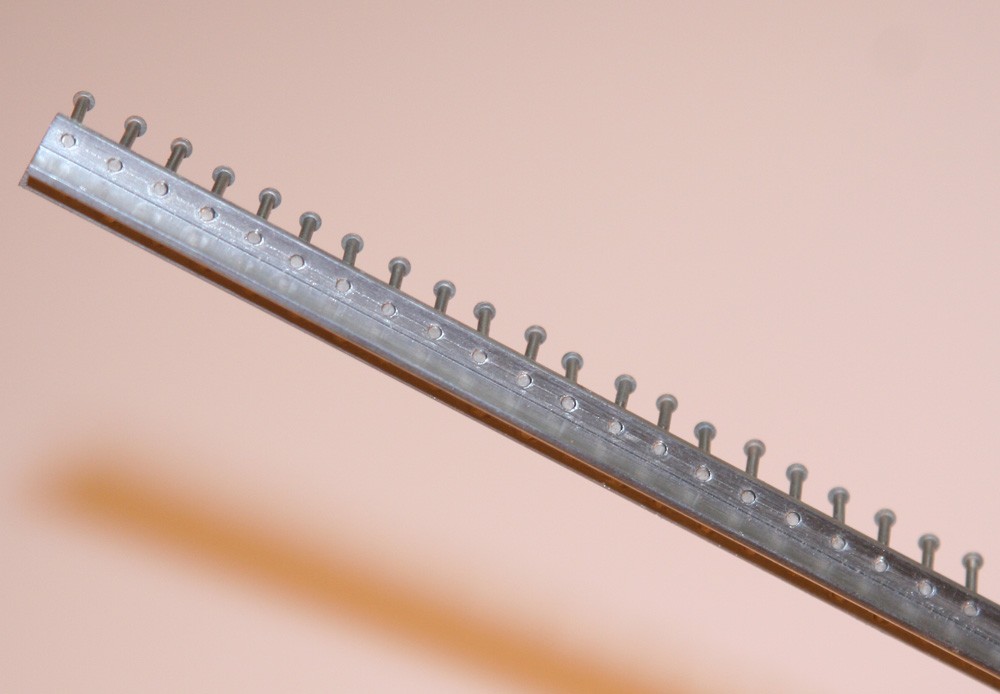
The first hurdle was to source L- and T-section aluminium from which to make the stringers, not easy given the relatively thin gauge of material required. After much searching I hit upon an answer in the form of those aluminium extrusions sold in long lengths in DIY stores for joining kitchen worktops and other domestic surfaces. Although much wider and deeper in section than needed (and plated to represent chrome) the thickness of the metal was within acceptable limits, so I decided to use it. However, I will leave the reader to imagine the hours spent manually cutting and filing the numerous stringers to size and on removing the resilient ornamental coating from the finished parts.
I made, drilled and installed the stringers over a period of months, gluing each one directly to the already emplaced alloy skin with slow-drying cyanoacrylate. As the photographs show, this primary bond is consolidated by many hundreds of 3/64-in. rivets, their pitches taken from the production drawings. The rivet heads are removed and the cut ends anointed with a tiny dab of cyanoacrylate glue before being inserted individually through the stringer and the laminated skin of the wing (see my previous blog). Protruding ends are cut off from the exterior wing surface, ‘irrigated’ with super-thin cyanoacrylate (which immediately soaks down into the balsa substrate) and sanded flush. The result is a strong and stable structure, none the worse for the lack of mechanical fixings in the true sense.
It may be worth mentioning here that in all but exceptional circumstances I avoid using power tools when drilling inside wheel bays, cockpit and other restricted areas. Most of the time there is simply not the room for a mini drill, even one with a right angle drive; but I have also learned through hard experience that power tools can jump and ‘chatter’, particularly in awkward places, and the resulting damage can be unforgiving. Thus while I drilled the stringers themselves on my bench top pillar drill, once each one was in position on the model, all holes were extended through the laminated skin using a hand held-pin chuck.
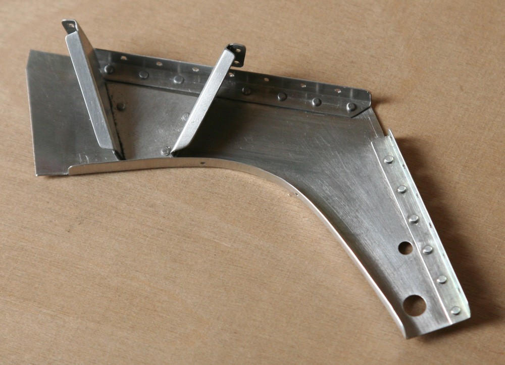
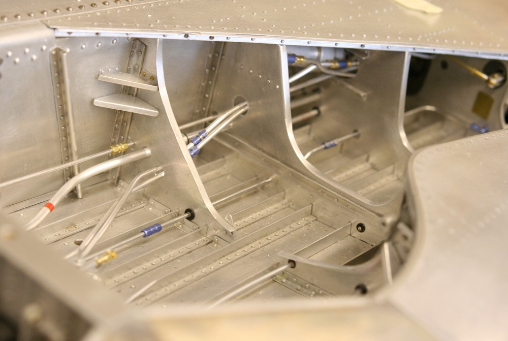
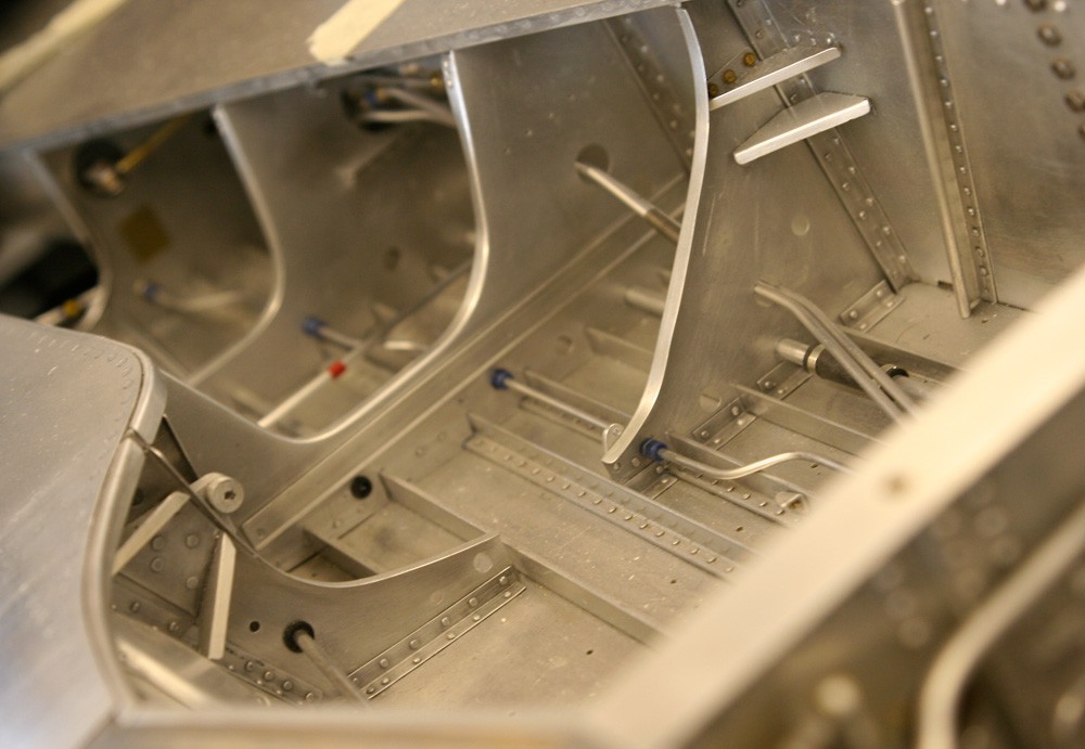
With the stringers in place I could begin fabricating the ribs, using scaled-down NAA drawings. No single one is identical to its neighbour, which, while precluding the kind of short cuts that aid production of multiple components, makes the job interesting and varied. Sheet metal work using litho plate is a joy, and this task was no exception. The arched shape built into each rib pair (port and starboard) required a simple hard wood or metal former over which to bend the curved flanges, otherwise the job was straight forward. Each rib assembly has numerous holes and slots, mainly for the aircraft’s plumbing and control cables, and where grommets were required I turned them in the lathe from black plastic rod. Most of the ribs are also fitted with various sorts of brackets, stays, mounting plates and cable guides, each of which has to be made and attached in advance using the drawings and photographs for reference. Only when complete was each rib sub-assembly installed, in a similar fashion to the stringers described above.
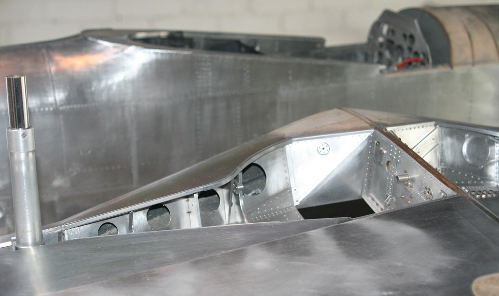
The accompanying images illustrate the extent of the task and the many and varied structural components and fixings that make up the basic airframe exposed within the wheel bays. The finish is left in bare metal, burnished with fine-grade steel wool but otherwise unpolished. Prominent on the exposed face of the main spar is a pattern of steel hexagon bolt heads. In the several years between their installation and completion of the model these oxidised somewhat, and with the accumulation of detail around them this was impossible to remove effectively. The result is not perhaps unrealistic, but had I anticipated it I would have considered some preventative measure.
Particularly prominent in the accompanying pictures are the large rectangular apertures cut into the upper wing skin both port and starboard, which in the real aircraft allow service access to the various radiator and oil system coolant lines, and other systems. I have more to say about these in my next blog, which outlines the very lengthy fitting out process that brought the wheel bays to completion.
Previous post

Retrospective: Wheelbay basics
Next post

Retrospective: Wheelbay fittings