Retrospective: Wheelbay fittings
Friday, 3rd January, 2014
An enormous amount of work went into equipping the Mustang’s wheel bays, much of it relating to the aircraft’s hydraulic group. It was a task tackled relatively early in the project, before the wings were skinned with aluminium and long before they were joined permanently to the fuselage. I spent well over a year of spare time fitting out the space with a seemingly endless catalogue of ancillary equipment and plumbing, and that over and above the time already invested in completing the structural features of the wheel bays, as described in my last blog.
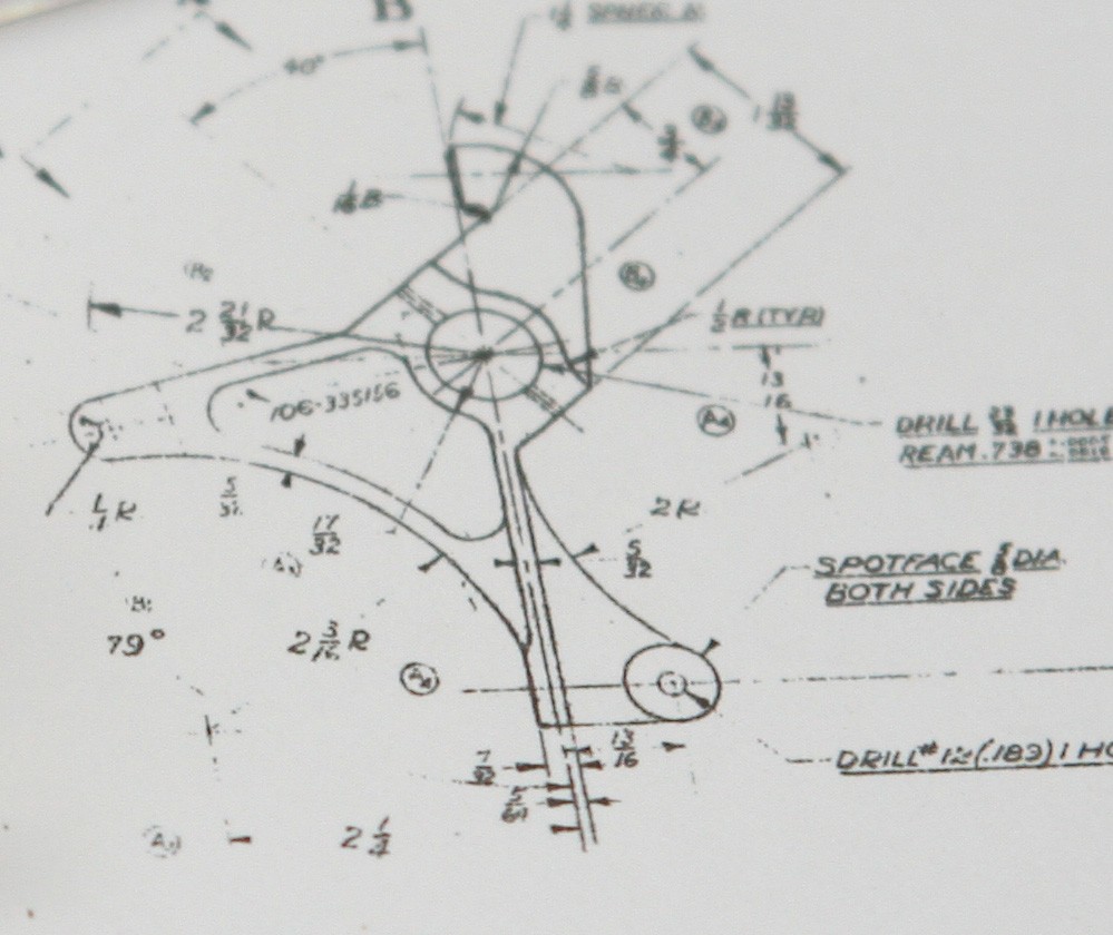
This stage of the model highlights once again the importance of comprehensive references. While photographs are invaluable for interpretation, only production drawings provide precise and unambiguous measurements that allow the model maker to start cutting metal with total confidence. A further invaluable asset was my P-51D Parts Manual, which is crammed with excellent line illustrations of very nearly all the airframe structural assemblies and its myriad fixtures and fittings. I do not pretend that I followed all of these to the letter. Given the complexity of many items of equipment within the wheel bays, this would have been entirely impractical, even in 1:5 scale, but the technical drawings, backed by my numerous other reference sources, including the Erection and Maintenance Manual, enabled me to represent each component at least to something approaching first-order realism, and to ensure that everything scaled with everything else.
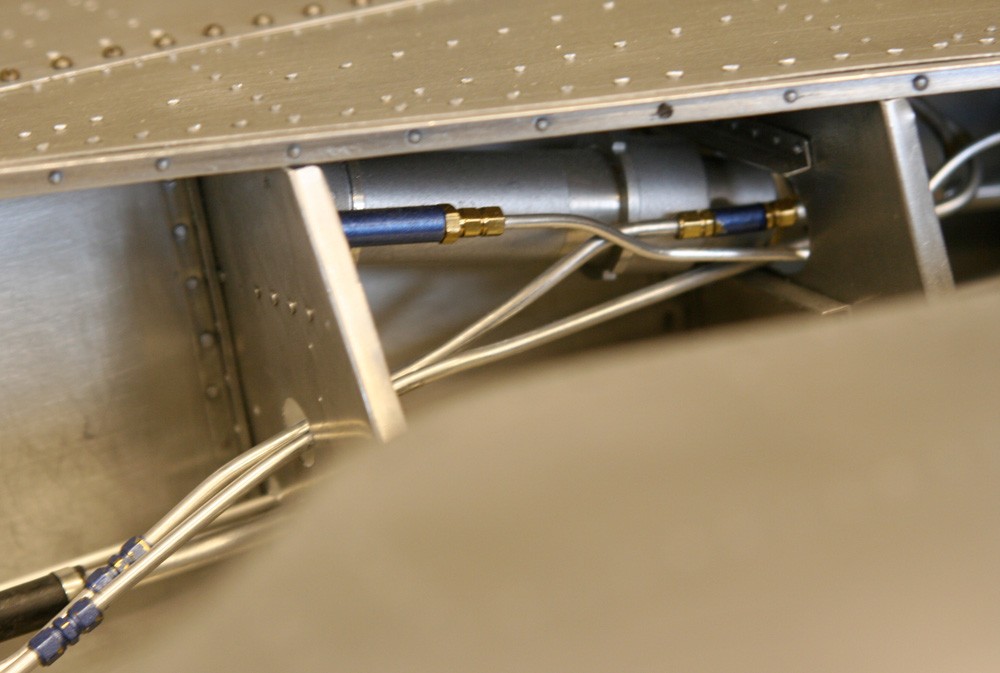
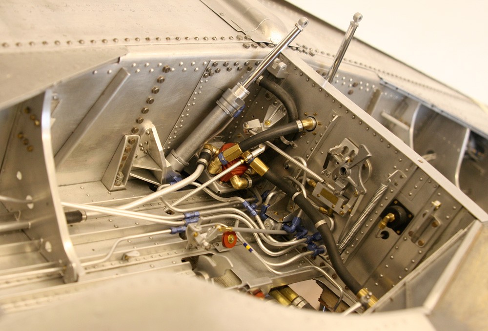
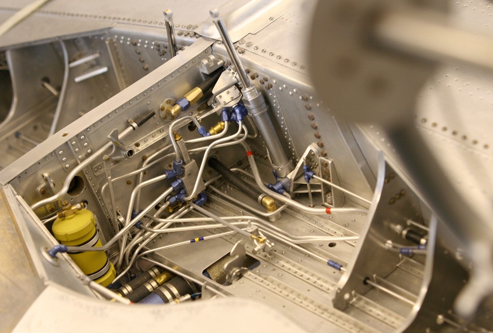
Yet that said, and while all the various systems in the wheel bays, including fuel and hydraulic lines, are indicated schematically in GA drawings, it is only from photographs that the model maker can really make collective sense of things, and particularly the tangle of pipe-work and hoses. Photographs clarify the run of the hydraulic and fuel lines in three dimensions, and how one relates to its neighbour within the confined space; they show the paths they take around unrelated components, or through successive wing rib assemblies, the position of clips, grommets and pipe unions, the surface textures of hoses – even the colour-coded tape used to differentiate between systems (This colour-coding system is also tabulated in the Maintenance Manual.).
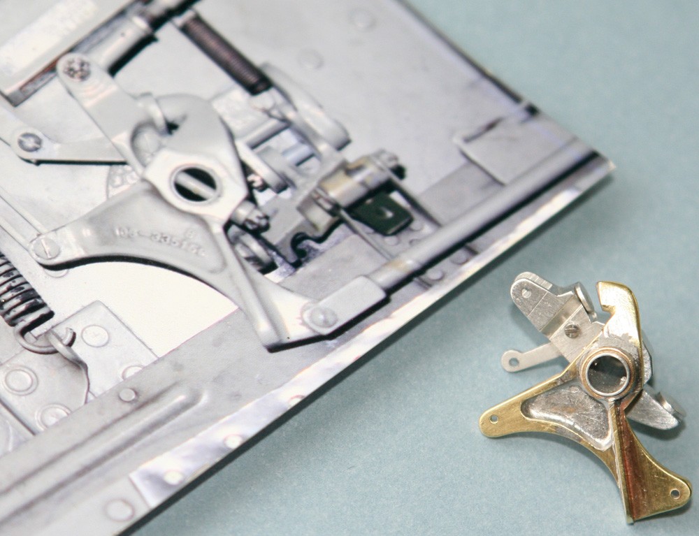
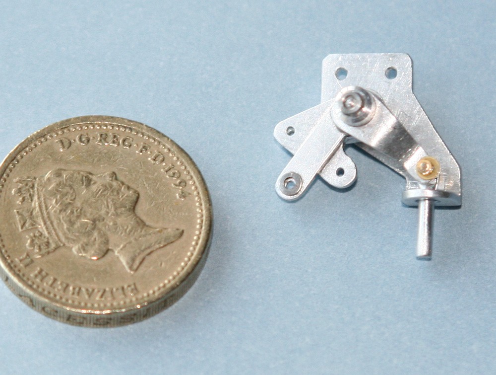
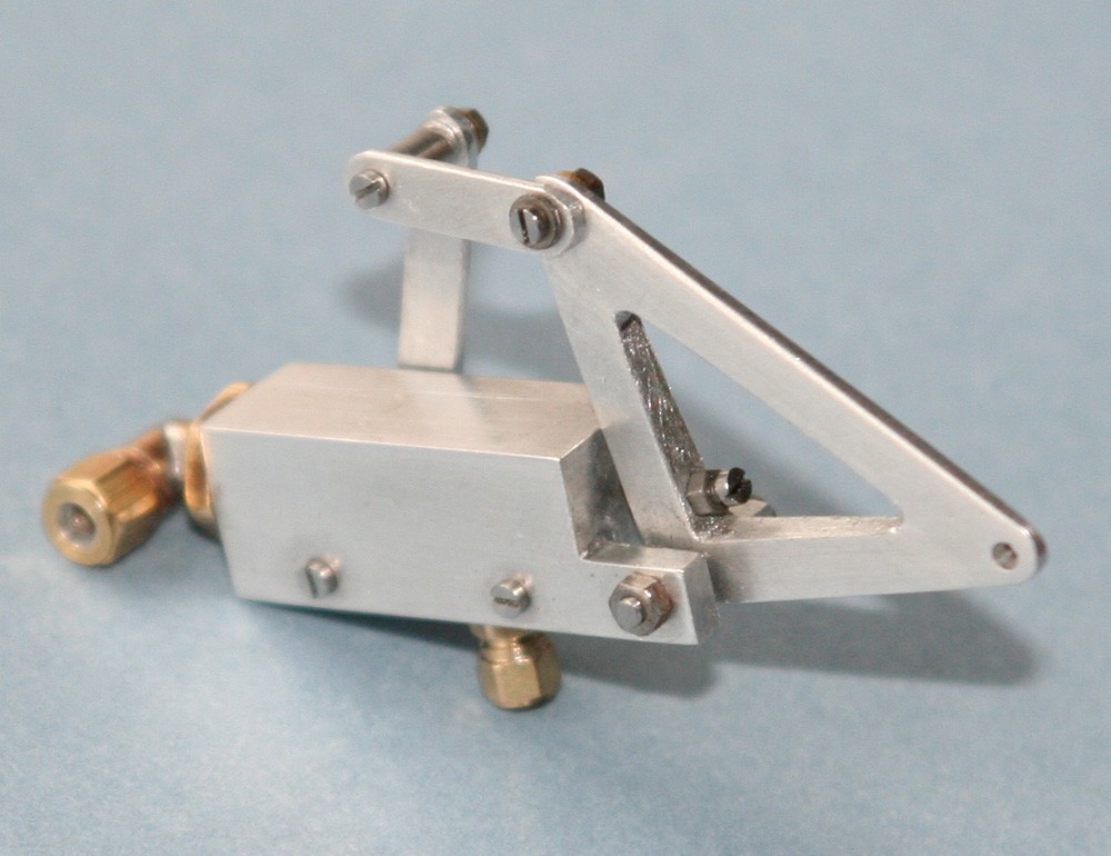
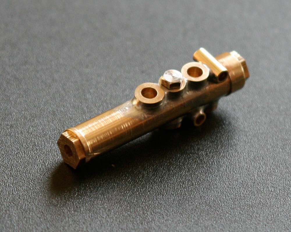
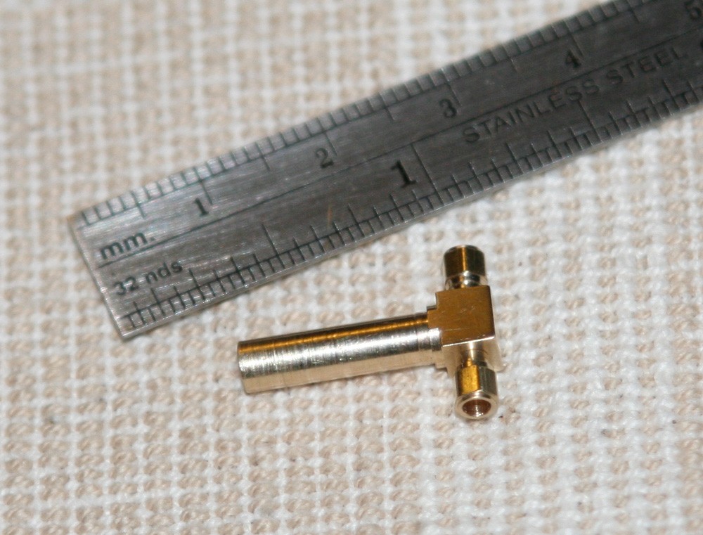
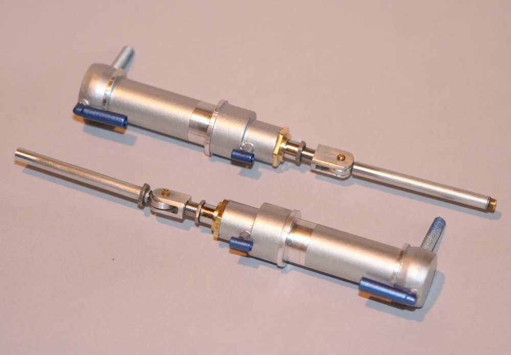
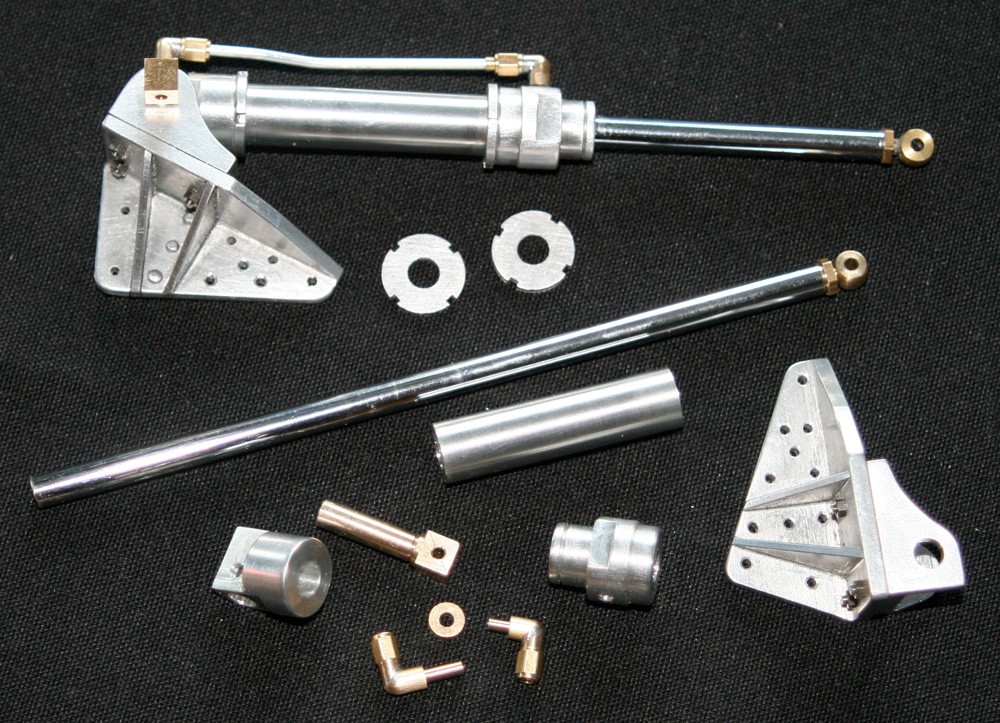
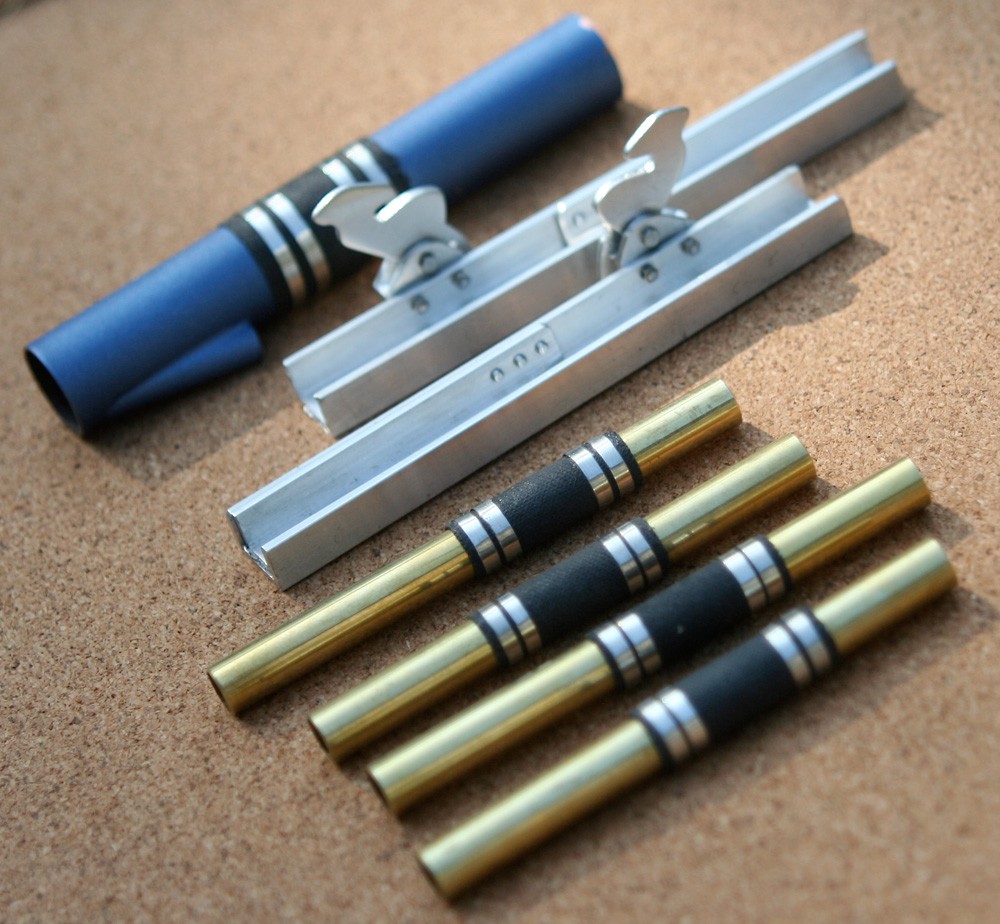
I do not propose to describe the making of all the various ancillary equipment that is crammed into the Mustang’s wheel bays. My pictures and captions exemplify some of them and the techniques used; they also emphasise the predominant use of metals – mainly aluminium and brass but also copper and steel. In the main, the pipe-work is made from several diameters of thin-walled aluminium tube of the sort found in hobby stores. This material bends easily and without specialist equipment, although where a radius is tight I inset lengths of styrene or even brass rod which prevents the tube from kinking. The ubiquitous two- and three-way pipe unions are turned from brass hexagon and sprayed automotive metallic blue (an attractive detail adopted from the Tullius restoration, but probably not a feature of production aircraft!)
Clearly, it would be foolish to pretend that this kind of work – even to the technically undemanding standard of a static (as opposed to working) model – could be attempted without machine tools. At the very minimum, a small lathe and bench-top drilling machine are indispensable; a mini milling machine, or milling attachment for the lathe, is close to a necessity.
Yet to equip such a workshop need not cost a fortune. Without exception, everything in the model’s wheel bays was made either with hand tools, or on small bench-top machine tools, which can be purchased new for hundreds rather than thousands of pounds. With the exception of my German-built jigsaw, all my machine tools are of Chinese manufacture. They are not the best, but easily good enough for the work I do; and if truth were told, their accuracy comfortably exceeds mine! I am not waving a banner for Chinese imports, but I am saying that the availability of such tools brings model ‘engineering’ within the budgets of far more people today than was true for my father’s generation.
So, while completing the wheel bays called for a great deal of patience and perseverance, and a tolerably well equipped workshop, it also came with one very significant advantage: variety! Unlike so many tasks required to build a large-scale model aircraft, which demand mind-numbing repetition, most fixtures and fittings here are ‘one-offs’; not only that, the content and arrangement of installations and plumbing in the port wheel bay differs markedly from that in the starboard wheel bay. All in all, this was a thoroughly interesting, absorbing and challenging chapter of the build.
-
Previous post

Retrospective: Wheelbay structure
-
Next post

Retrospective: Main doors